At my QTH, I am quite space constrained with only 620 square metres of land. The layout of the house leaves little flexibility in erecting long straight antennas. For a number of years I’ve had a horizontal V shaped antenna with a tuner to match it to multiple bands. This worked OK, but I found that it was quite deaf when I started chasing low powered SOTA stations (being in a noisy urban environment and in the bottom of a valley don’t help either!)
After much reading and thought, I decided to give a full wave horizontal loop antenna with open-wire feed a go given the apparent noise reducing characteristics of this type of antenna. I already had three support poles 9m tall for the old antenna, so simply added a 4th pole to create an approximately rectangular shape with approximately 63m perimeter. Unfortunately this isn’t quite enough to resonate on 80m, but would work for all the higher bands.
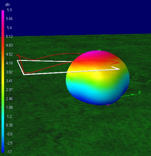
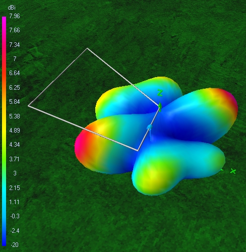
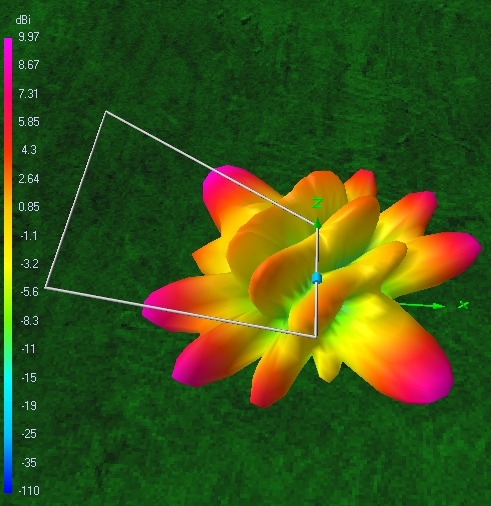
I modelled it in 4nec2 and found it looked viable for the HF bands. Here are the modelled far-field patterns for 40/20/10/6m:
40m NEC2 model pattern – mostly an NVIS antenna given the relatively low height
20m NEC2 model pattern – now quite directional, but much lower radiation angle
10m NEC2 model pattern – could work quite well for DX with a low radiation angle and enough lobes to cover most directions adequately

6m NEC2 model pattern – almost omnidirectional with a low radiation angle and reasonable gain
For the antenna to be a multi-band solution, an antenna tuner is required and to minimise loss, an open wire feeder into a 4:1 balun and 1:1 choke balun was used.
The baluns were designed as current baluns according to Sevick (“Transmission Line Transformers”, 4th ed, Jerry Sevick, W2FMI, Noble Publishing). The 4:1 balun was built as a parallel-series combination of two FT140-61 toroids with 11T of RG180 (95 ohm) coax. The 1:1 balun was simply 13T of RG316 (50 ohm) coax also on a FT140-61 toroid. This balun was on the low impedance side of the 4:1 balun obviously.

Baluns, feeder disconnect relays and surge suppression components mounted in a weatherproof diecast box.
The baluns were mounted in a weatherproof diecast box on the wall of the house with a low loss coax (FSJ4-50B hardline) feed covering the approx 5m to the tuner in the shack. This would minimise the loss due to SWR between the baluns and the tuner.
The open wire feed line was 300 ohm open wire that I’d had for some 25 years of origin unknown.
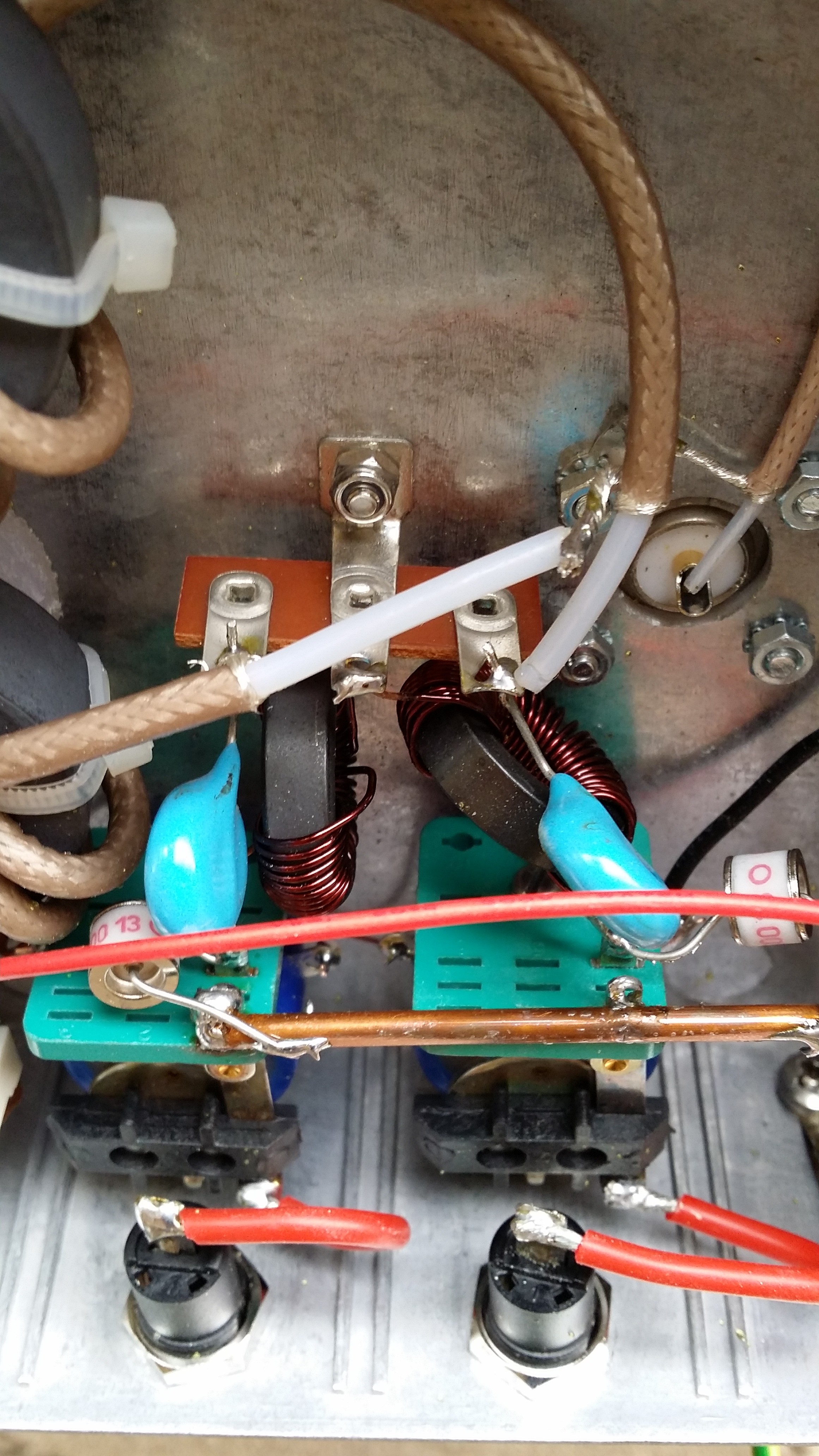
Disconnect relays and surge suppression components close up
Whilst lightning is fairly rare near my QTH, I thought it prudent to add a grounding relay to the box and also some surge suppressor components (a DC blocking capacitor, gas discharge tube and DC grounding choke to each side of the balanced line). This required a couple of open frame RF relays (sourced from Surplus Sales of Nebraska) and a control cable (I used weather proof CAT 5 cable for this to allow additional relays to be added later).
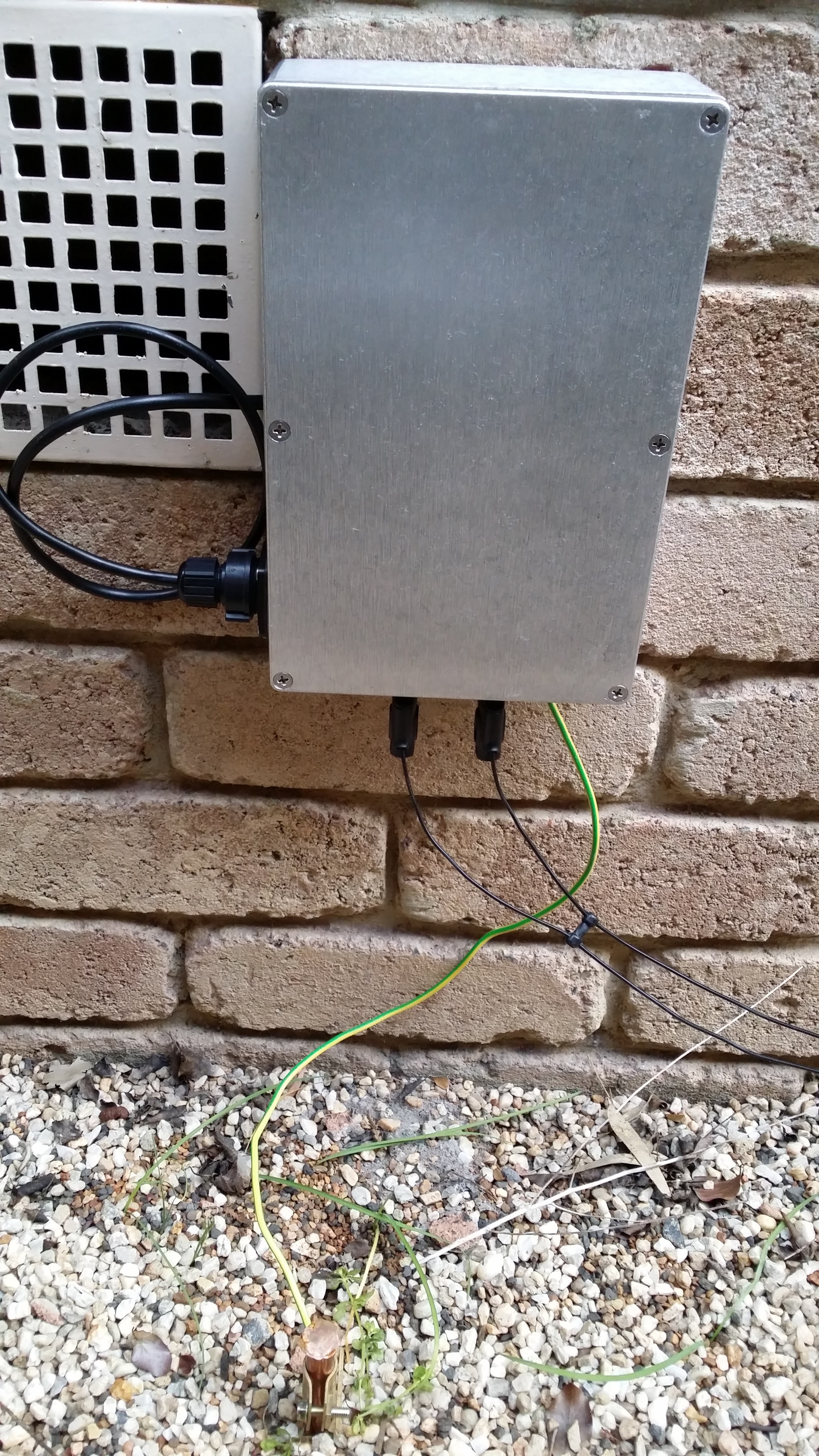
The complete feedline termination box with the CAT 5 control cable coming in the left side and the open wire feeder coming through banana jacks on the bottom
The complete antenna is now operational and provides the following impedance at the end of the coax in the shack:
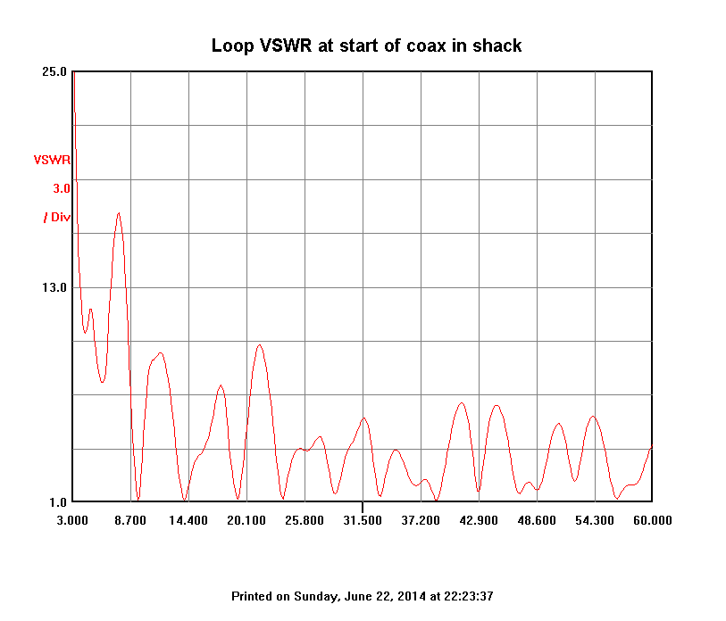
SWR sweep at the shack end of the coax. The SWR is low enough from 7 MHz up to allow the antenna tuner to match it
So far the antenna is working well with a definite improvement in signal levels across all bands. The next step is to add a loading coil to allow the antenna to be used on 80m…
Great article. Thanks..
I would like to employ this sort of solution to my location in North Western Puerto Rico. I am very new as a radio operator but am eager to try.
Do you think a roof top loop in the shape of my home at about 20 feet above cement roof would work? I have A/C units and some solar panels on the roof as well. The shape of my home is almost rectangular at about 95 feet by 35 or 40 feet.
any guidance you can give would be most appreciated.
Best regards, Robert
Hi Robert,
Sorry for the slow reply. Yes, I think this would be worth trying. I calculate that you could get a loop of nearly 115m in length which should be possible to tune from the 80m band up. 20′ above the roof should be high enough to work well I think. The only unknown would be whether the A/C and solar panels were generating significant noise which may couple to the antenna. You’ll soon find out though and if that’s a problem you could potentially improve that with some appropriately placed ferrites and/or shielding. Good luck!
73
David
VK3IL
Hi,
Have you tried to work in the 50 MHz band to transmit? Does it perform well?
Thank you, I have 2 loops 113m and 40m, but I dont have 6 meter band to try them on that band.
Hi David,
I have used it once or twice on 6m, but my QTH is in the bottom of a valley, so quite a poor location for VHF bands. It should work, with a rather spiky radiation pattern which is roughly omnidirectional (see the 4Nec2 plots).
73 David VK3IL