Having recently built a MTR2 3-band CW transceiver, I was keen to make band switching on a mountain top as simple as possible.
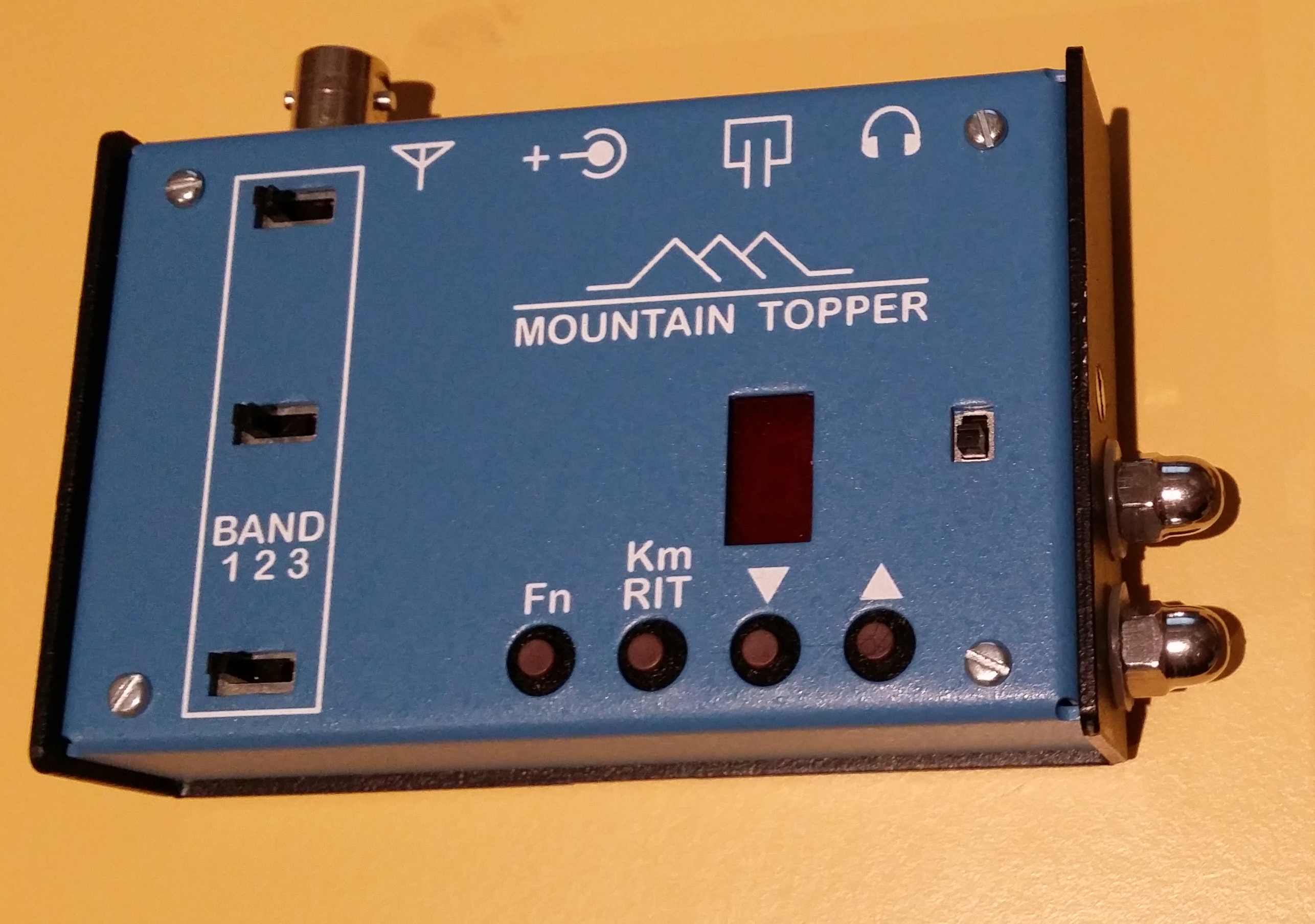
My MTR2 now with a touch paddle
I have been using a 40m End-Fed Half Wave (EFHW) antenna very successfully for the last few months and I wanted to extend the design to multi-band whilst avoiding the need to take a tuner along. The matching unit I use requires no tuning which makes setup very quick.
The simplest method of making an EFHW multi-band is to put links in it to allow the antenna to be adjusted in length easily. This is OK, but is likely to require lowering a squid pole to reach the links to change bands – not ideal, but very simple.
The other method is to segment the radiator wire with traps for the various desired bands (noting here that I’m considering non-harmonically related bands). The challenge for a lightweight antenna is how to build traps that are compact, light and reasonably robust.
In the end I decided to build the latter and to build it to cover five bands: 40/30/20/17/15m. This was due to the fact I have my eye on a compact 5 band SSB/CW rig that covers those bands (the LNR Precision LD-5).
To keep trap losses low, it’s important to keep the component Qs as high as practical and also allow for the voltages and currents that appear across the traps at planned operating power levels. I used a target power level of 100W so that I could use it with a typical 100W transceiver if necessary.
I decided that to keep the traps as small as possible, I’d look for surface mount Hi Q transmit-rated capacitors and then build the coils around them. I found some excellent capacitors in the form of the ATC 100B series. These are porcelain dielectric SMD devices rated at 1kV and are good for more than 10A. However, they are not cheap at around A$2.40 each! Getting them is also challenging and the only place I could find them available in small quantities was from RF-Microwave.com in Italy (here’s the link: RF-Microwave).
I found an excellent coil former in the guise of a 4mm “rigid riser tube” used for micro-irrigation systems and widely available at Bunnings/Masters etc. These are about 4mm ID and have an OD of 6.4mm – the ATC capacitors fit comfortably inside this tube.
I wound the coils with 1mm enamelled copper to keep the RF resistance low and fed the ends back into the tube to make the connections to the capacitor. Soldering the capacitors on is a little tricky and you need to be careful not to put too much strain on them as they are only rated for 5 lb maximum tension on the end caps (I know, I broke one).
The following photo illustrates a completed coil winding with capacitor inside together with one of the capacitors for comparison.
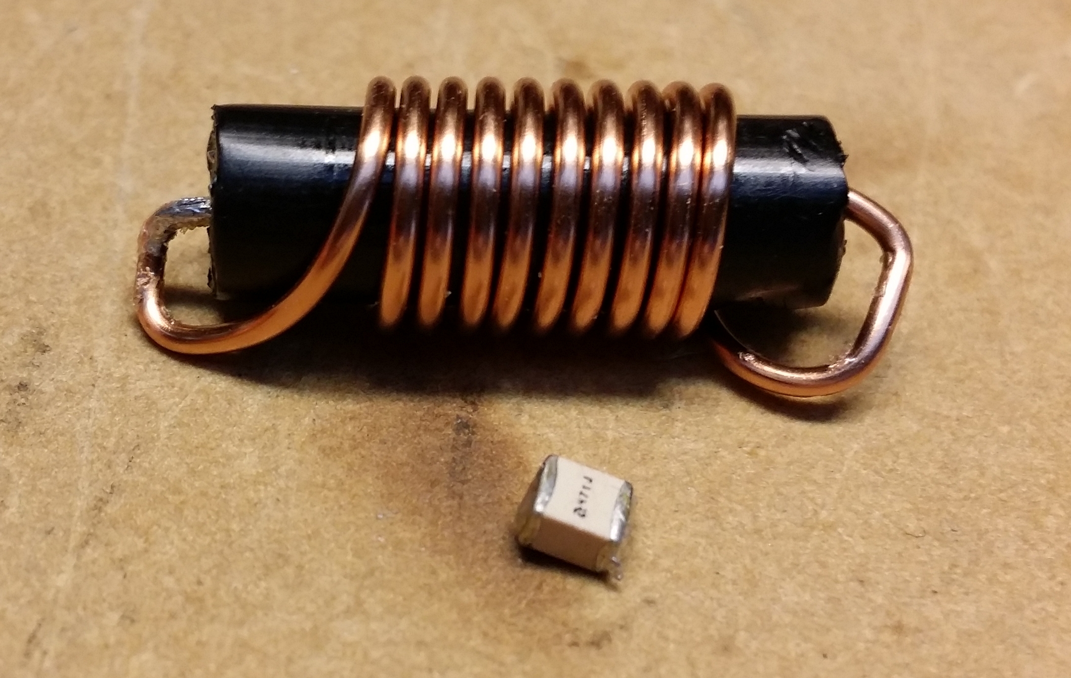
Trap and ATC100B capacitor for comparison
The traps were aligned using my N2PK Vector Network Analyser by adjusting the turn spacing to achieve resonance at the required frequencies. I found that adding protective heatshrink over the trap dropped the resonant frequency by up to 60 kHz, which required some adjustments to get them right. The frequency is also very sensitive to the coil spacing due to the low L, high C trap design. I kept the inductance low to keep the coils physically small.
Here’s the details for the traps:
| Band | Measured resonant freq [MHz] | C [pF] | L [nH] | Turns |
| 15m | 21.148 | 220 | 260 | 7 |
| 17m | 18.151 | 220 | 350 | 9 |
| 20m | 14.165 | 220 | 580 | 15 |
| 30m | 10.090 | 470 | 530 | 15 |
Note that the number of turns in the table above are for a 6.4mm diameter former. A larger former would need less turns.
As you can see from the photo above, these traps are not designed to be strung in-line without some additional strengthening. To keep with the philosophy of ultra-light and ultra-compact design, I went searching for clever methods of strain relief and found on the AT-Sprint Yahoo group a reference by WT5RZ to a neat method: using braided fishing line to take the strain. It is quite simple in theory: use a nail knot to attach the braid to the antenna wire on either side of the trap leaving a little slack in the wires attaching to the trap.
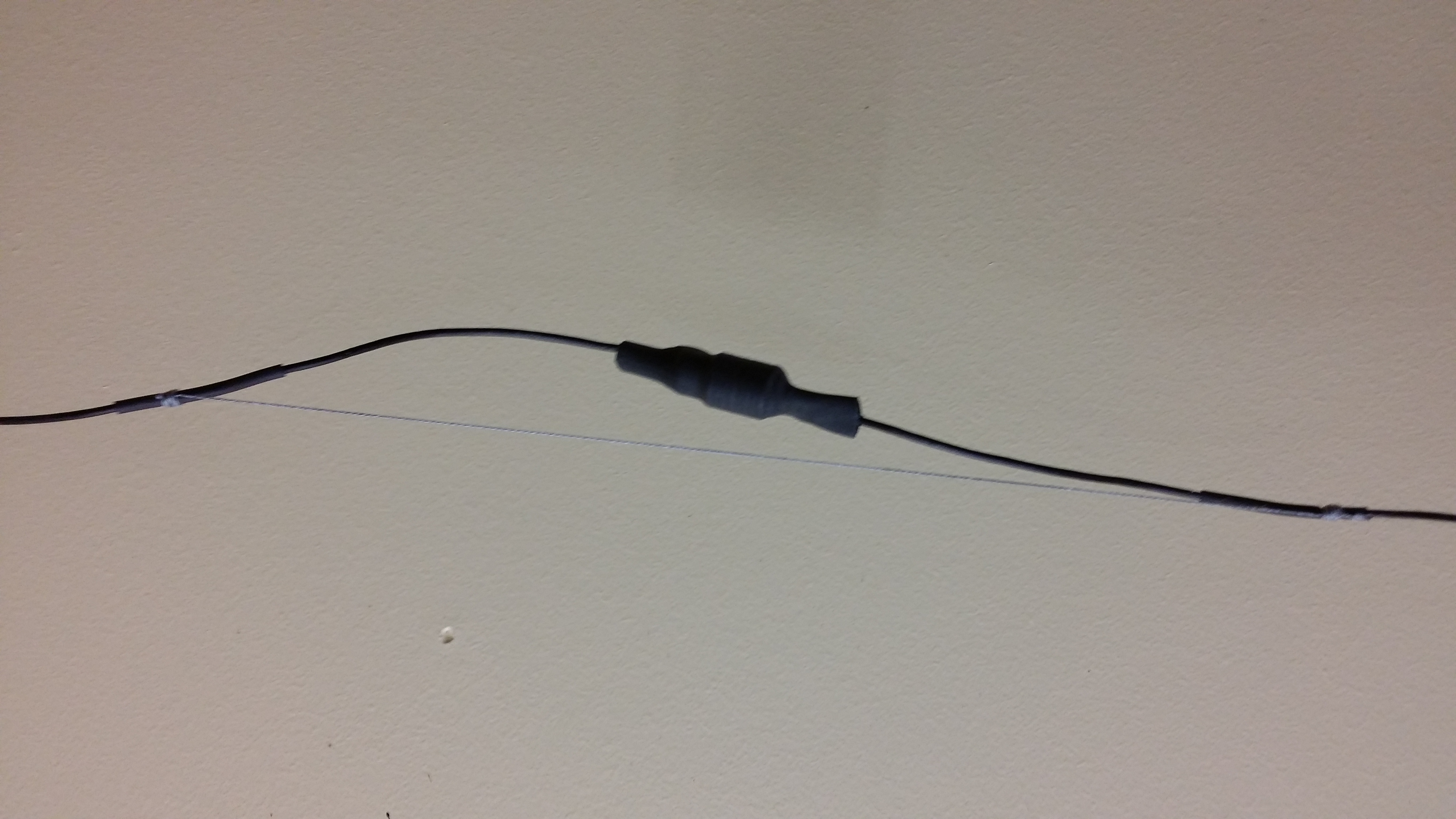
Fishing braid used to provide strain relief for traps
- Use thick braid for both strength and also to prevent it cutting in to the wire insulation too much – I used 50lb braid
- Put some heatshrink over the wire to add both something soft for the braid to grip and also to protect the antenna wire insulation from the braid
- Be careful with a heat gun around braid – it melts. Better to apply the braid after all the heat shrinking is done to avoid weakening the braid
The wire lengths were calculated using a 4nec2 model and came out as follows together with the final adjusted lengths after trimming (note that they are significantly longer than modelled):
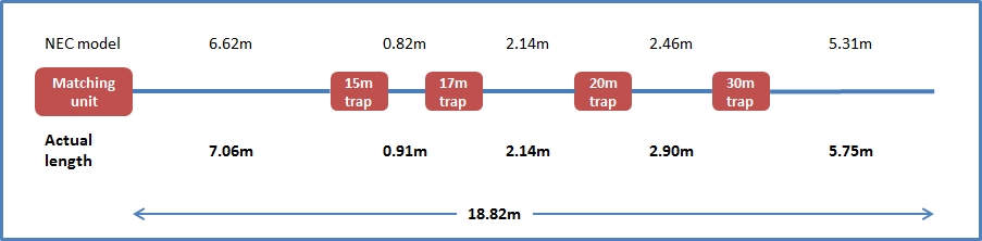
Note that the modeled wire is a DX-Wire like wire of Chinese origin that has a PE sheath and 6-stranded plated copper wires with an aramid strengthening element. Outer diameter is approx 1.6 mm and it is very light at 4 g/m. If you use a different type of wire, then these lengths could be significantly different.
The NEC2 model is at the bottom of this page if anyone wants to play with it.
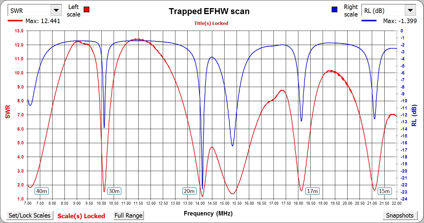
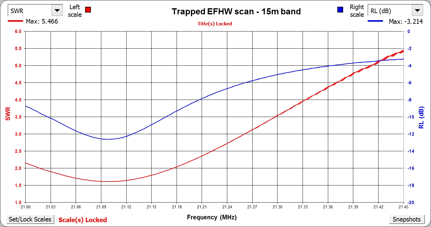
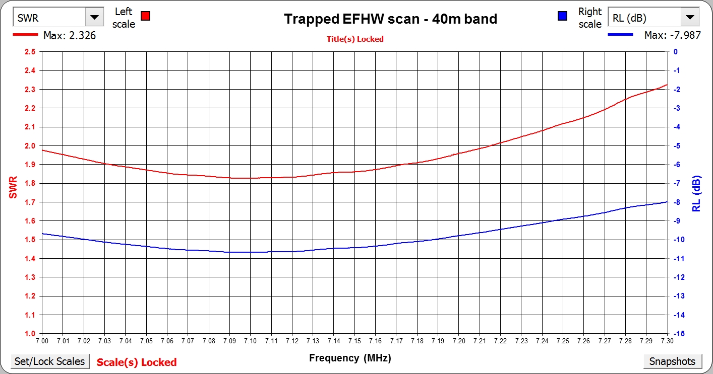
Full scan of my trapped EFHW in an inverted Vee configuration
The plot above was created with Z-Plots from Dan Maguire AC6LA.
As you can see, the SWR is better than 2:1 for parts of each of the bands of interest using a fixed EFHW matching unit (described here). It will be interesting to check it out in the field as I’ve found that SWR on an EFHW is dependent on both the surrounding environment and the height of the antenna ends from the ground. It is also dependent on the coupling of the feedline to the ground (given the matching unit I built uses the feedline as the counterpoise – I’ve found this works fine in practise in the field).
I should be able to use the upper portions of 20m and 15m with the help of an ATU if necessary. The detailed SWR plots for each band are in Appendix 1 below.
Here are some photos of the completed antenna rigged to a squid pole in the garden.
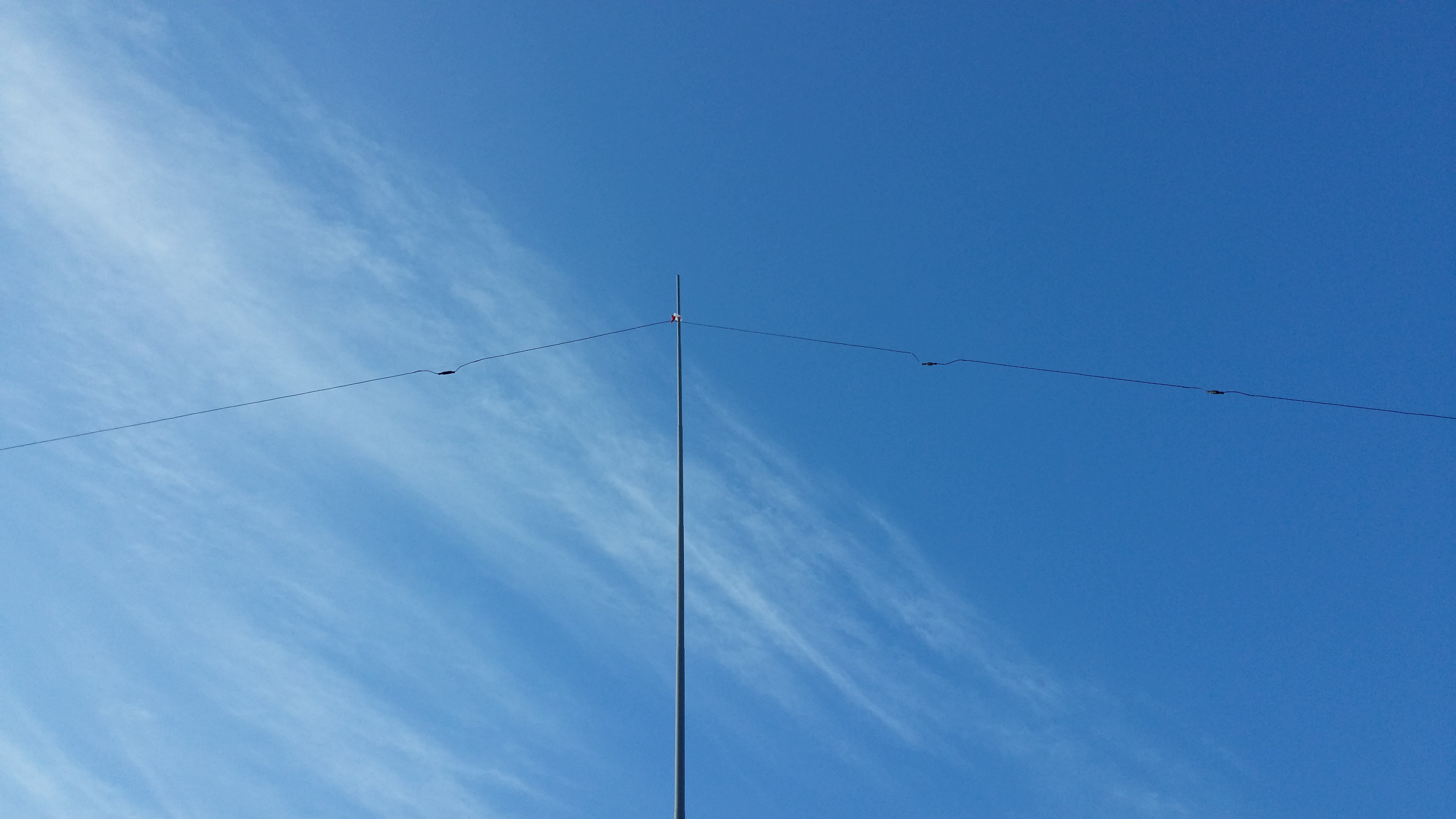
Apex of inverted-V showing three of the traps.
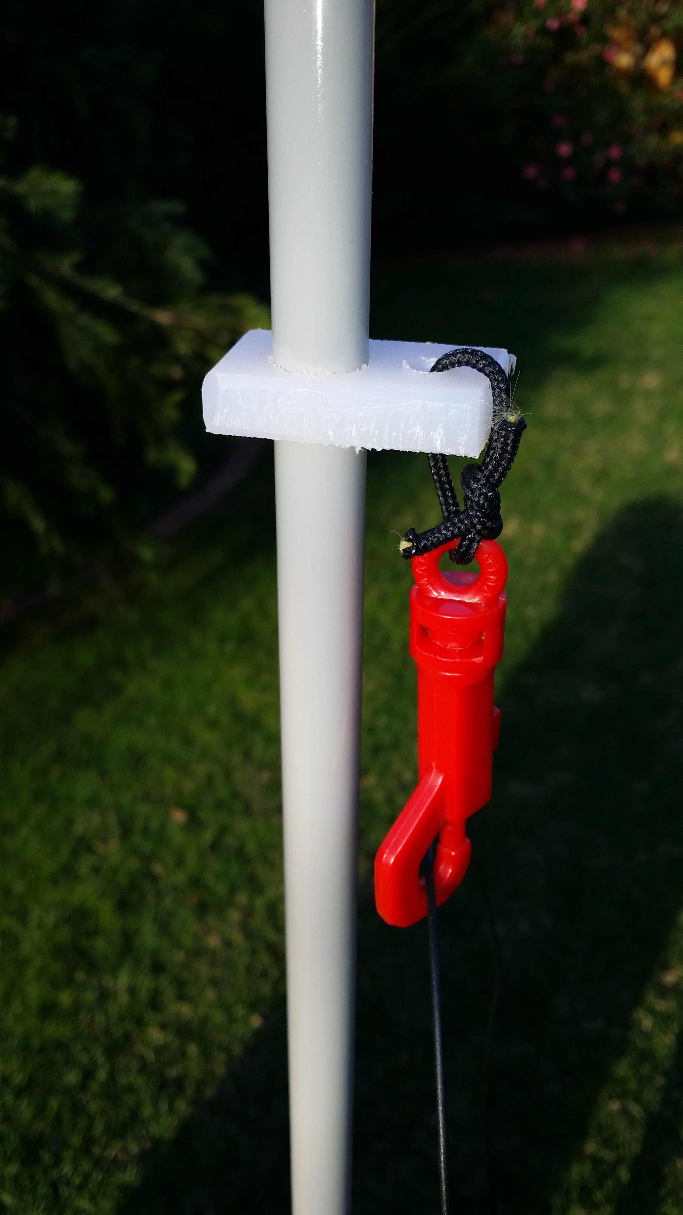
Attachment point for wire to squid pole. It is simply a piece of polyethylene kitchen chopping board drilled to the size of the squid pole section together with a plastic dog clip to hold the wire.
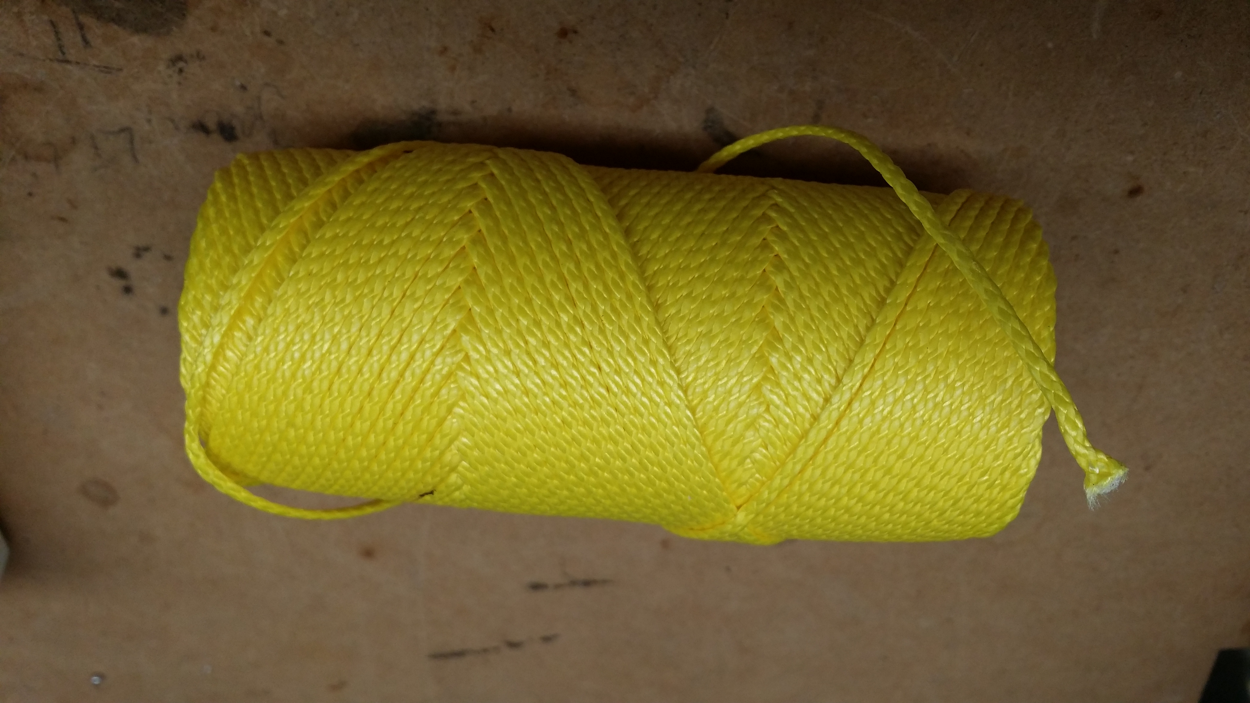
Zing-It is an extremely tough but light cord ideal for portable antennas
The end support cord for the antenna is an interesting product called Zing-It. This is sold for arborists to use with throw weights to get them into trees. As such it is incredibly abrasion resistant and strong. It’s 1.75mm diameter and has a rated load of 230 kg! It is also very hard to cut with a knife – even a Stanley knife had to be used like a saw to cut through it. It weighs only 1.65g/m.
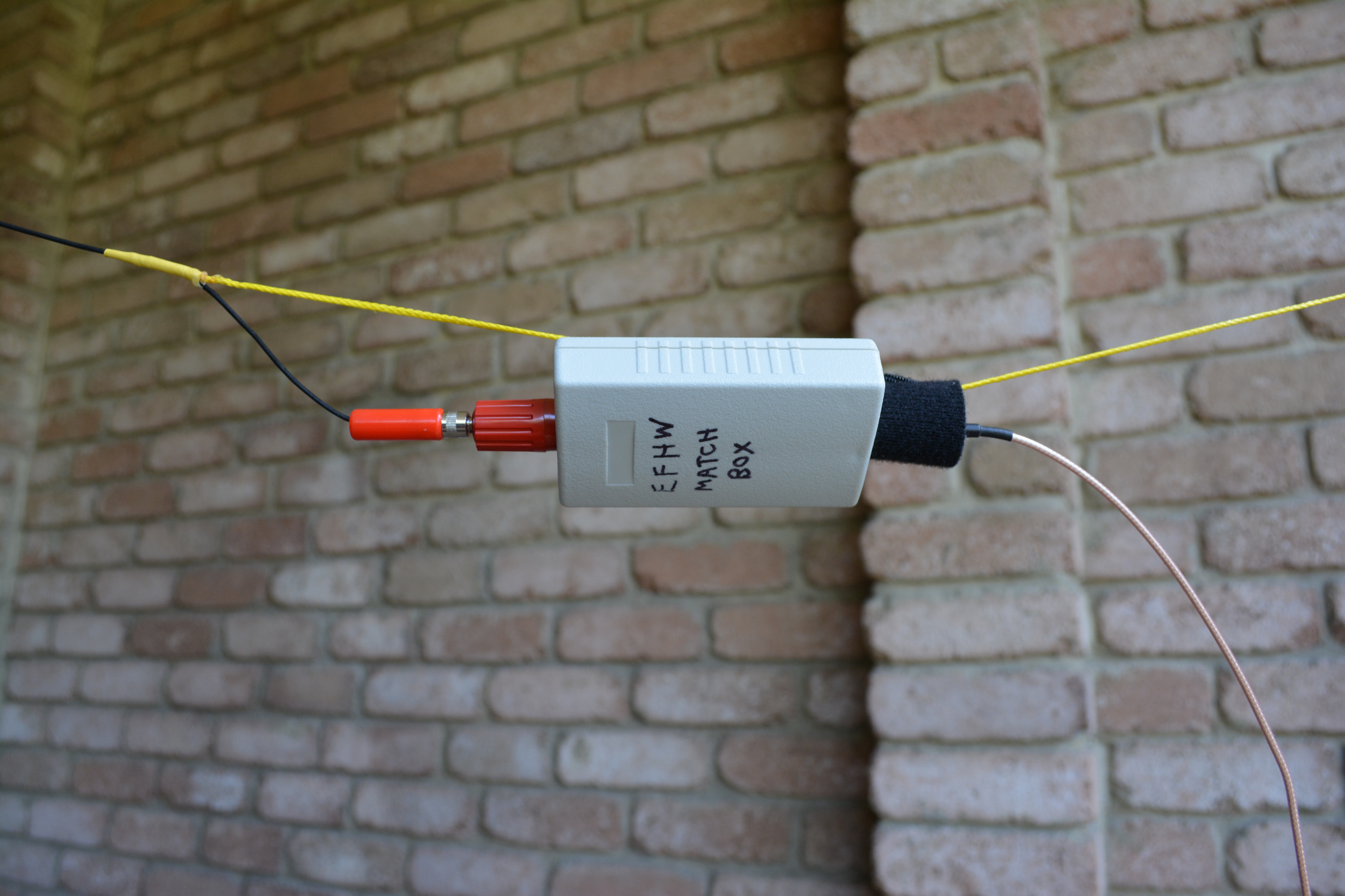
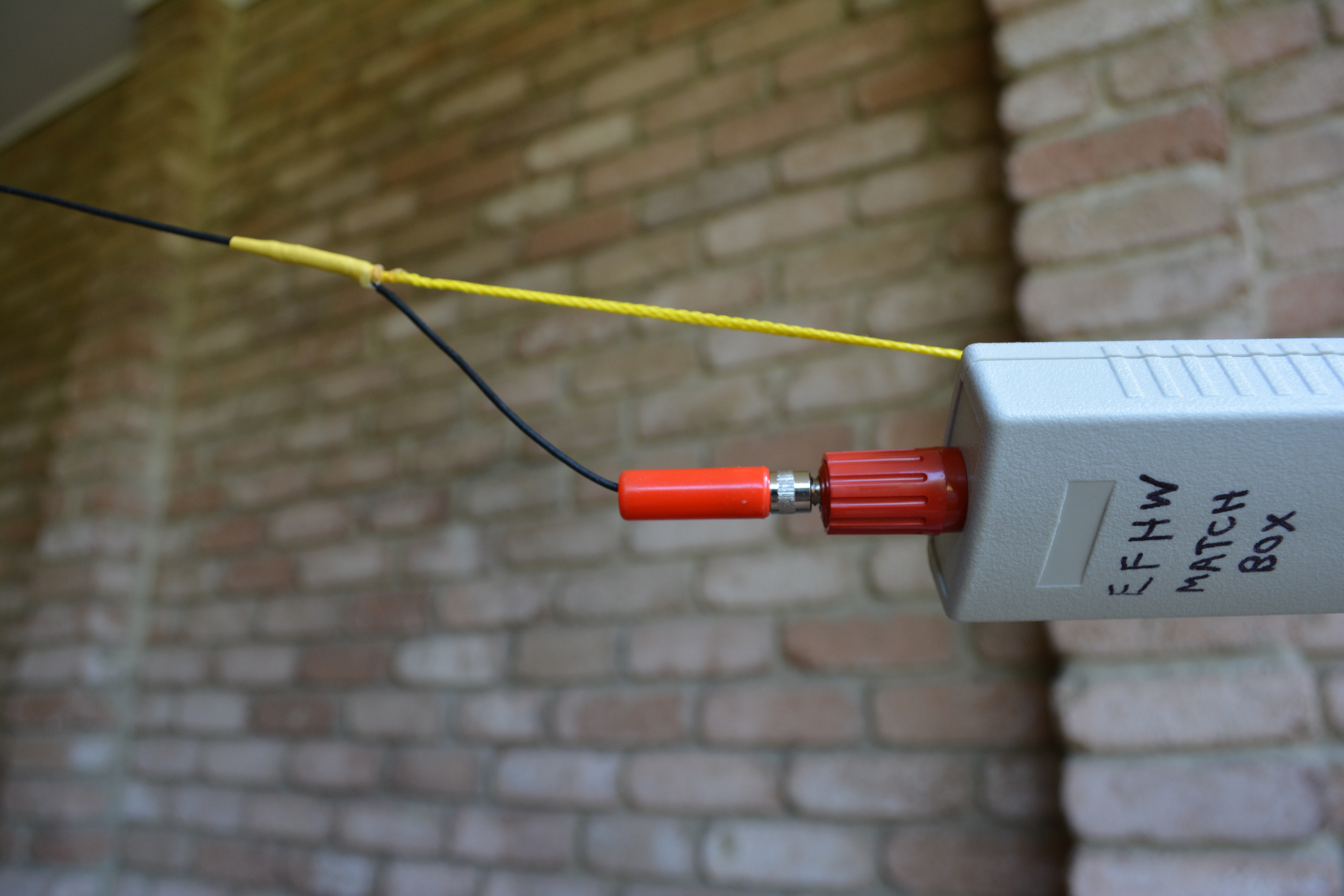
The matching unit is attached to the support cord with a simple piece of velcro tie wrap
The feed end of the antenna is attached to the cord by passing the wire through the centre of the cord and bringing it out through the weave. Araldite and heatshrink again finish the job
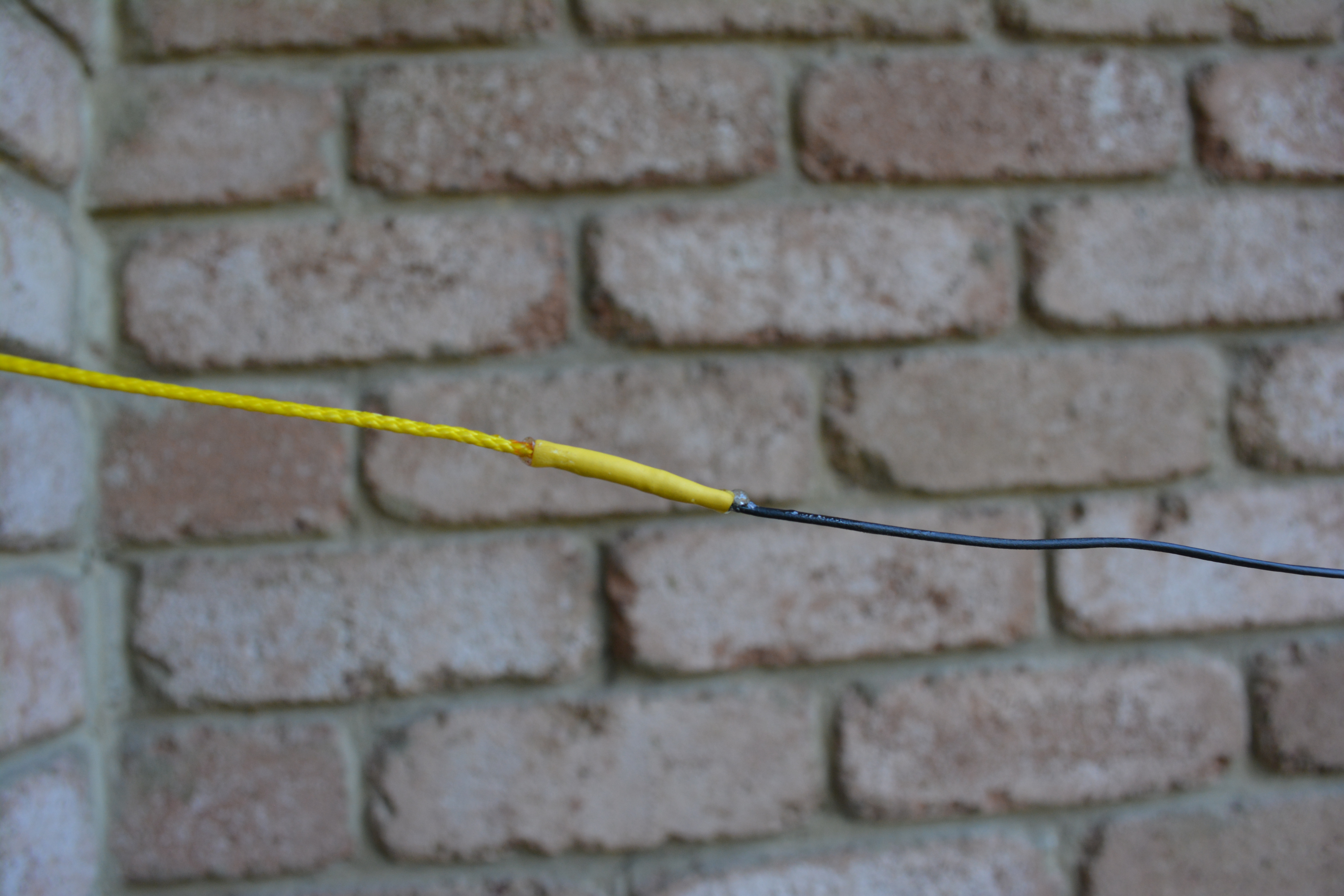
Connection to the end of the antenna wire is by opening the end of the cord tube, inserting the wire and then using Araldite or similar to glue them together. Heatshrink finishes it off neatly. Thanks to Allen VK3HRA for the idea on this!
I now need to try out the antenna in the field and see how well it works in practise!
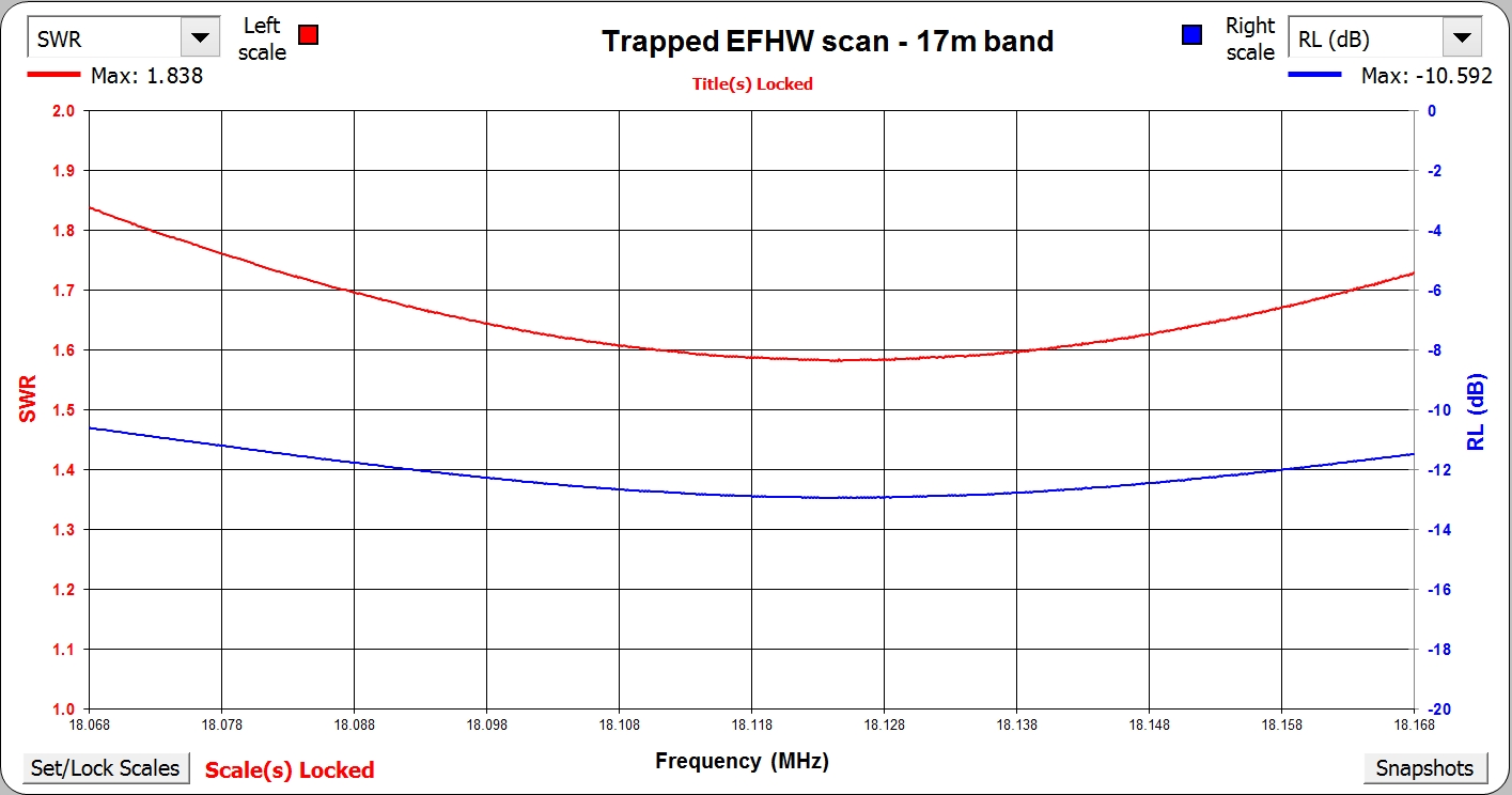
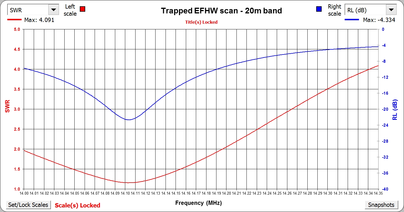
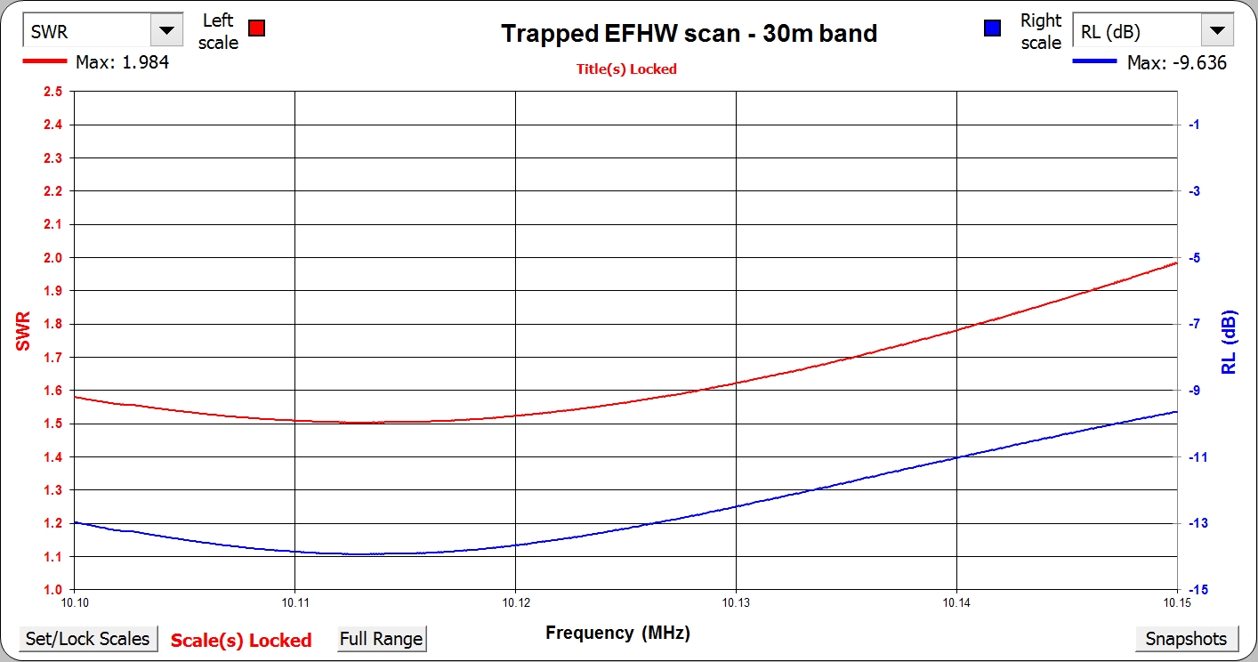
Appendix 1 – Detailed SWR plots
Here are the detailed plots for each band for reference:
Appendix 2 – NEC2 model
Here’s the NEC2 source for the model. Note that it is modelled as a vertical with the feedpoint between the bottom of the antenna and ground. I haven’t found a better way to model an EFHW in NEC2. Thus it will not be a good model of the radiation pattern when deployed as an inverted V, but seems to be OK to calculate lengths of wire segments. Also note that you need to set the characteristic impedance of the system to whatever you think the end impedance of the EFHW may be – I found 4700 ohms was OK for modelling purposes – you are really looking for SWR minima to optimise the antenna segment lengths rather than predicting the absolute SWR value.
If anyone has a better way of modelling an EFHW, I’d be keen to hear it!
Here’s the model:
CM Trapped EFHW for 40/30/20/17/15m
CM
CE
SY L15=6.622073 'Length of 15m element
SY L17=0.819581 'Length of 17m element
SY L20=2.144196 'Length of 20m element
SY L30=2.459585 'Length of 30m element
SY L40=5.313973 'Length of 40m element
SY Ltrap=0.043 'Length of trap
SY L15s=0.043 'Start of 15m element
SY L15e=L15 'End of 15m element
SY L17s=L15e+Ltrap 'Start location of 17m element
SY L17e=L17s+L17 'End location of 17m element
SY L20s=L17e+Ltrap 'Start of 20m element
SY L20e=L20s+L20 'End of 20m element
SY L30s=L20e+Ltrap 'Start of 30m element
SY L30e=L30s+L30 'End of 30m element
SY L40s=L30e+Ltrap 'Start of 40m element
SY L40e=L40s+L40 'End of 40m element
GW 1 100 0 0 L15s 0 0 L15e 0.00025
GW 2 1 0 0 L15e 0 0 L17s 0.00025 '15m Trap
GW 3 10 0 0 L17s 0 0 L17e 0.00025
GW 4 1 0 0 L17e 0 0 L20s 0.00025 '17m Trap
GW 5 20 0 0 L20s 0 0 L20e 0.00025
GW 6 1 0 0 L20e 0 0 L30s 0.00025 '20m Trap
GW 7 50 0 0 L30s 0 0 L30e 0.00025
GW 8 1 0 0 L30e 0 0 L40s 0.00025 '30m Trap
GW 9 50 0 0 L40s 0 0 L40e 0.00025
GW 10 1 0 0 0 0 0 L15s 0.00025 'Feedpoint
GE 1
LD 7 0 0 0 2.4 0.00025 'DX-Wire UL wire
LD 6 2 1 1 100 259nH 220pF '15m trap
LD 6 4 1 1 100 351nH 220pF '17m trap
LD 6 6 1 1 100 579nH 220pF '20m trap
LD 6 8 1 1 100 528nH 470pF '30m trap
GN 2 0 0 0 4 0.003
EK
EX 0 10 1 0 1.0 0 0
FR 0 0 0 0 14.1 0
EN
like the way you have made it up David nice work
Do you have a source for the “chinese wire”
Vince,
I got my wire as part of a bulk purchase organised on the Australian SOTA Yahoo group, so don’t actually have the original source for it.
73
David.
peter VK3PF has a large quantity of this wire if you speak to him feel sure he can help you out
73 Rod
I might suggest you get in touch with Peter VK3PF he purchased a large amount of this wire from china and should be able to help you out
Pingback: Bill Head and Pyramid Hill - 29 September 2014 - VK3IL BlogVK3IL Blog
Pingback: Mt St Phillack - 26 Sep 2015 - VK3IL BlogVK3IL Blog
Can you show more detail how you soldered to the capacitor inside the form?
Joe
W3JDR
Hi Joe,
Yes that was a little tricky. I don’t have any photos of that part and the traps are now sealed up. The basic process was to wind the coil, remove the form and pre-tin both the capacitor terminals and the ends of the coil. Then attach one end of the cap to the coil and slip the form back into the coil. The lengths of the coil ends are cut so that the cap is close to one end of the coil. By pushing the form to the far end of the coil, the unsoldered end of the cap is just proud of the form allowing you to tack the coil end to the cap. The form can then be slipped back to fully cover the cap and the whole unit encased in heatshrink to hold everything in place. Hope that helps!
73
David.
really interesting
I did for time being matchbox with fixed capacitor and all is resonant close to 1:1.1 on 20m with a single wire sligtly below 10m (found by trying)
works well with FT-817 and 5W was hearing well stations from VK in France and could made some QSO on SSB within 2500 kms range (propagation was not great these days and BTW only 5W out…)
Now I am thinking about making it multibander (20/17/15) – your ideas are precious for further experiences
Hi Thomas,
Thanks for reading. It is still working well for me. For simpler trap construction, SOTABeams now has kits for small traps that also work well.
73
David
VK3IL
Hi David, love EFHW – got impressed by your design and build it too. Great idea to use the ATC capacitors. Wanted to build it for 100W. But at 50W the isolating trap gets so hot that the solder melts in seconds and the trap fells apart. 30W is fine. Did you find the same ? Tested that with an EFHW for 40/30/20/17/15m. Interested in your comments. (I am Region Manager for SOTA DL/MF and created the DA/AV Region many years ago – which is in GMA now). 73 de andy DL2DVE
forgot to mention: modulation: continuous wave (carrier) for a few seconds. perhaps SSB with very very short peak power 100W works.. 73 andy DL2DVE
Hi Andy,
I built this antenna for predominantly QRP operation. Whilst I chose the capacitors with the potential to handle 100W, I think the design falls short. I have used it successfully with 50W SSB, but never actually tested at 100W level. I suspect that the Q of the coils are quite low due to their very small size and hence have high enough losses that the temperature rises you are seeing are quite plausible. It would be interesting to test with 100W SSB and see if the temperature rise is acceptable – uncompressed SSB has quite a high peak to average ratio.
73
David
VK3IL
thanks for the response David, fully aligned ! The ATC capacitors are a great asset, perhaps the design shall change a bit, capacitor outside the hot coil. Shall experiment with it, when/if I find the time. 73 andy DL2DVE
What is the procedure for determining the length of wires. Which do you adjust first and what order for the rest?
Hi Doug,
The lengths of the wires were calculated using the NEC2 model (included at the end of the article.) Essentially the wire segments must make up a half wave length at each frequency, but taking into account the loading of any traps – hence why NEC2 modelling is the most practical way to design it. In terms of adjustment, I built the entire antenna with wires a little longer than modeled and then trimmed them starting with the wire for 15m (the one 7.06m long on the diagram), then working outwards towards the end of the antenna. You need to have all the wires in place to trim as the further out wires do have a small effect on the tuning of the closer in wires. Hope that helps.
73 David VK3IL
Hi David,
It has been a long time since our Dallas NGN trip!
Love the trap design – I did my first at 14 yrs of age and spent a whole school holidays doing it just right. Yours reminds me of this!
Hope you are well and liked your recent AR article.
Cheers,
Phil
Hi Phil,
It HAS been a long time! Thanks for reading the blog. Hadn’t realised you had an amateur license. As you can see, I’ve been quite involved in SOTA of late.
73 David VK3IL
Very innovative design Dave, I made mine out of coax only, however, I can see as a SOTA enthusiast you wanted to keep the design lightweight.
Thanks
John
G4YDM
I don’t see any comments as to how you feel this is working and if the traps were a compromise? I was thinking of building similar using the SOTA traps. I was also considering two – one for 40/20/15 and 30/17/12.
Hi Don,
Yes, I realise I never went back and updated this article with field experience. In short, yes, it works fine for QRP. As you will have seen from the comments, it doesn’t work at higher power as the trap losses are sufficient to cause overheating at a 50W continuous carrier. This obviously indicates that the traps are lossy which is not unexpected given the small coil size and correspondingly low Q. The compromise is definitely the size of the traps – I was aiming for as compact an antenna as possible for SOTA, so was prepared to accept the loss to enable a no-tuner multi-band setup. The other practical problem I found was that the combination of fishing line and loops of antenna wire made it snag easily in trees, so not ideal from a deployment perspective. I’ve shifted to primarily using a no-trap EFHW with antenna tuner as I now use a KX2 as my main activating radio.
The SOTA Beams traps are neat and should work slightly better than this design. Bear in mind that all small traps are compromises and will be consequently power limited.