
My first couple of SOTA activations used a SOTABeams Band Hopper III linked dipole. This worked well, but with two wires, a 10m coax and an extra guy, it took a bit of time to set up and it was easy to get all the wires tangled if the wind got up. I started reading about alternatives and decided an End-Fed Half Wave (EFHW) looked like a good option.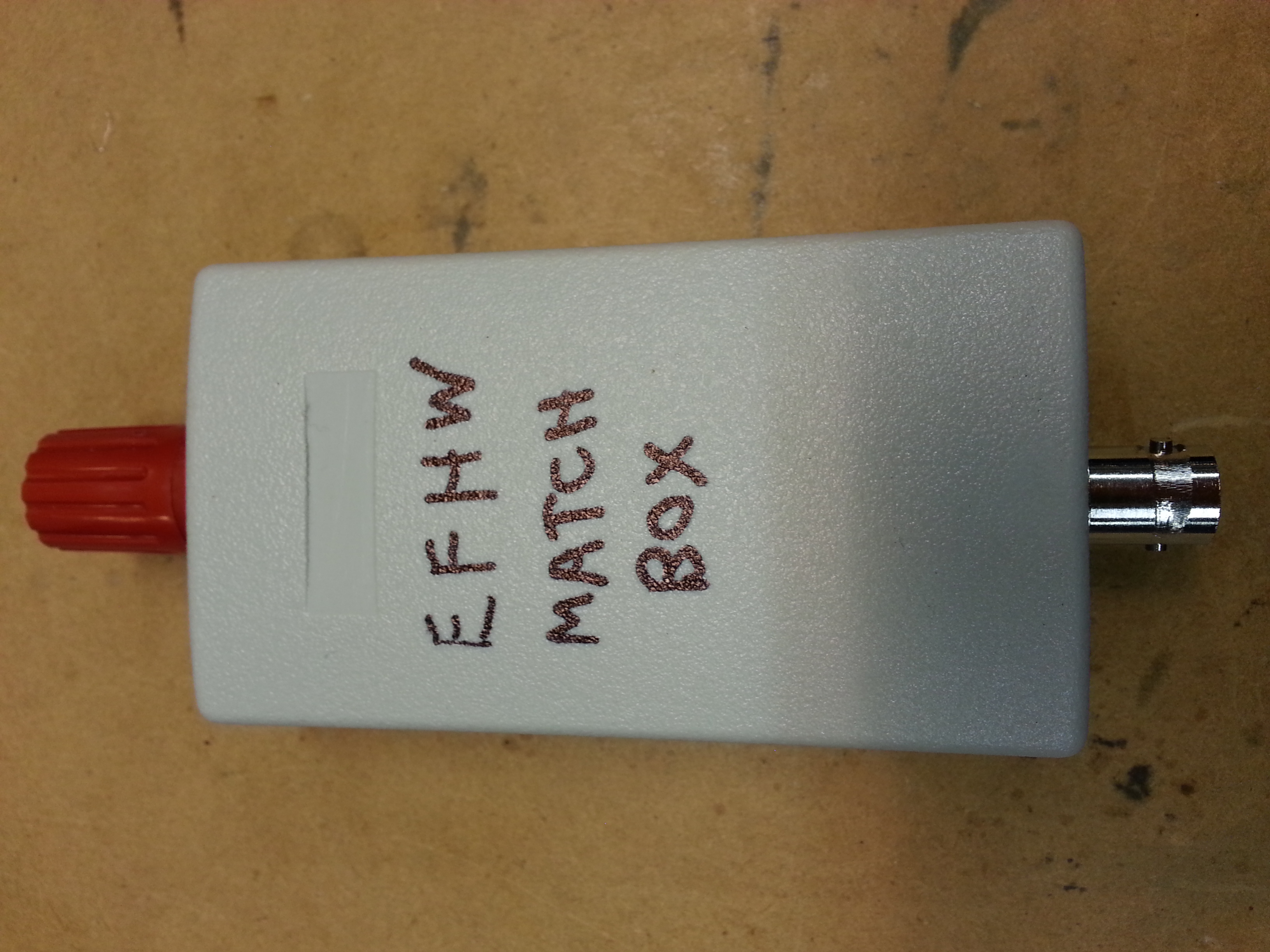 The benefits are:
- One matching unit could feed a range of elements that were just simple wires (or could be multi-band with links or traps)
- The matching unit was low to the ground in an inverted V configuration and hence could be fed with a short coax
- The antenna could be used as either an inverted V or a half wave vertical on the higher bands
The challenge with the EFHW is feeding it as the end is a high impedance point (apparently between 2000 – 6000 ohms depending on the surrounding environment). I explored a range of matching unit designs. They seem to fall into two main categories:
- A transformer with a tuned circuit for the secondary
- A simple impedance transformer with a fixed capacitor across the primary
The first model is well described by AA5TB (Steve Yates) along with several example designs. The main limitation of this design is the need to tune the tank circuit for the operating frequency in use. Designing a single matching unit that will cover a broad frequency range is challenging. It also requires a tuning capacitor that is capable of quite high voltages that appear at the end of a half wave antenna. The typical construction of such a matcher uses a Polyvaricon capacitor which limits the power to QRP levels only (noting the high voltages present at the end of the antenna).
The second design is that used by PAR EndFed antennas. It is a broadband match design with no tuning required and this appealed to me. The trade off is that you can’t get the SWR down to 1:1 except by luck, but it is possible to get a SWR below 2:1 for most frequencies of interest with a typical half wave wire. I found a couple of good references to such designs by Dutch hams here and here. They include details of creating multi-band EFHW antennas using this matching unit.
I followed the Dutch designs quite closely, but experimented a bit to see if the 150pF capacitor is the right size. In my case, I used a FT140-43 toroid (wound with a layer of Teflon tape for protection of the toroid and enamel coating) with a 3:24 turns ratio wound using 1 mm enameled copper wire. Here’s a photo of the competed unit:
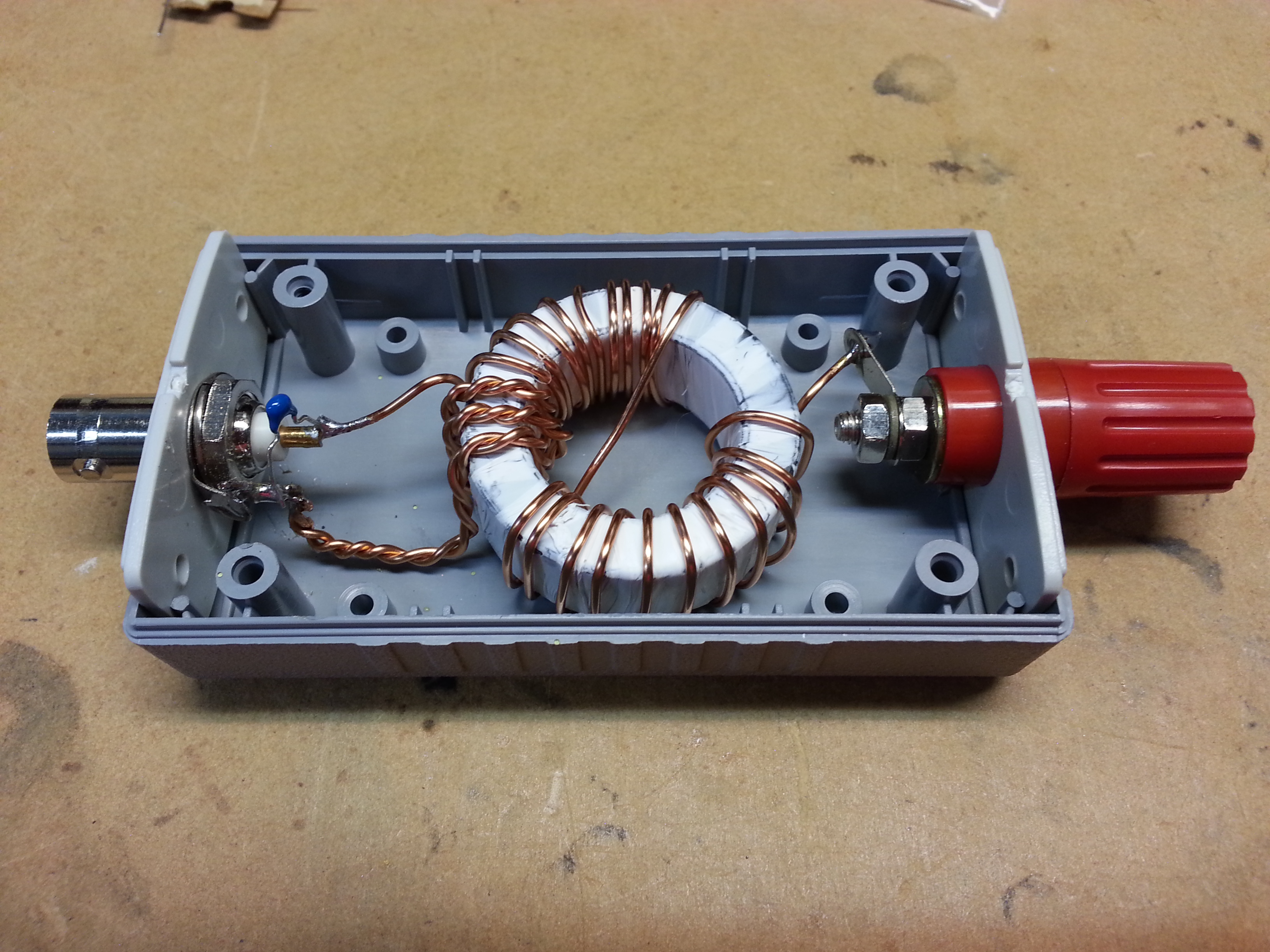
My EFHW match box. 3:24 turns ratio on a FT140-43 toroid with a 150pF capacitor across the input.
I experimented by attaching a load resistor between the output and ground for a range of possible antenna impedances from 2200 to 6800 ohms. Here’s a series of SWR plots across the HF bands from 80m to 10m with first no capacitor and then a range of capacitor values as detailed on the images.

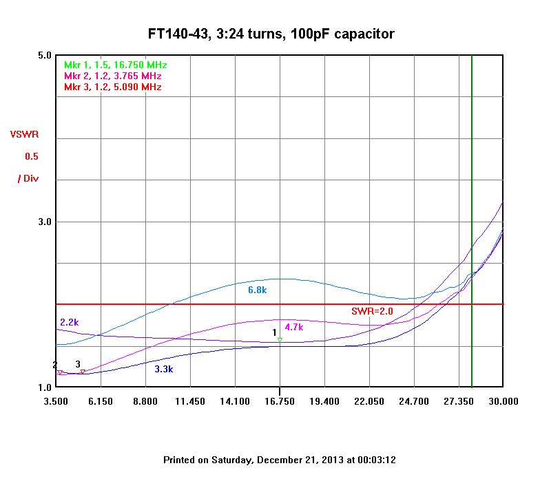
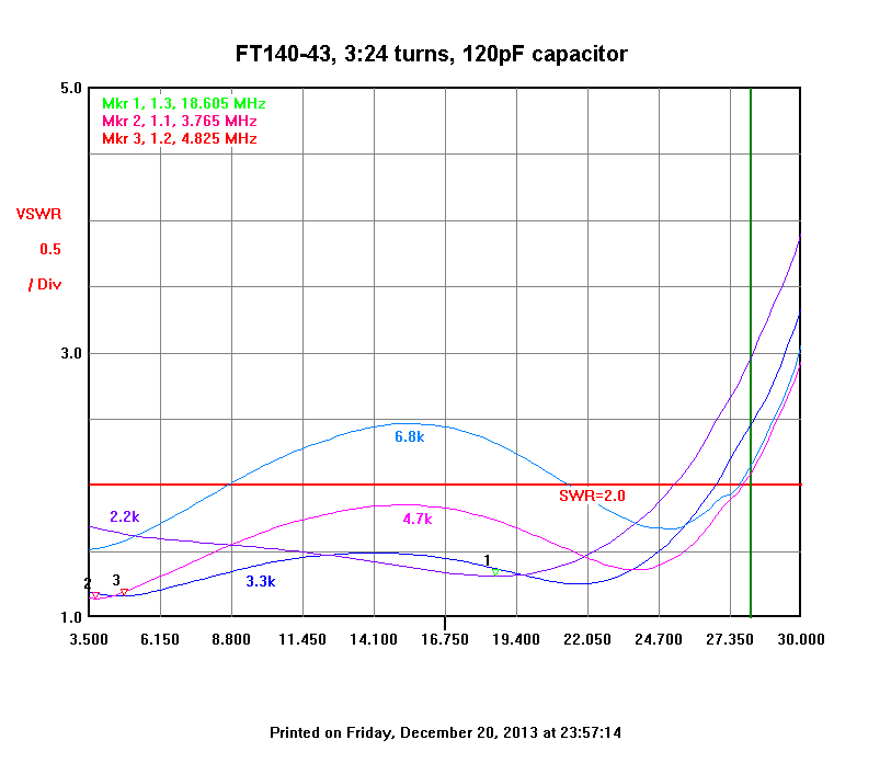
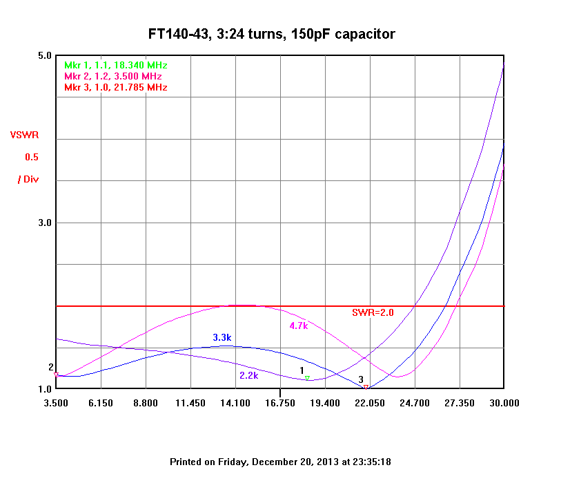
As you can see, the capacitor is clearly necessary in this design and 100 pF allows a better than 2:1 match across most HF bands and impedance values. Whilst 150 pF provides a better match at some frequencies, the 100 pF seems to provide a more even performance over a wider range of loads and frequencies. Values above 150 pF resulted in much worse plots and weren’t recorded.
It would be possible to replace the fixed capacitor with a variable capacitor (such as a Polyvaricon). This may allow the SWR to be reduced through tuning for the specific frequency and antenna impedance at the time. I haven’t tried this as the goal was to get adequate performance with no tuning needed. The advantage of this design with a variable capacitor is that the voltage across the capacitor is much lower than if the capacitor is on the high impedance side of the transformer. Hence a Polyvaricon in this position would likely be fine with 50W or possibly even 100W (with the sections wired in series).
You’ll see that there is no counterpoise with this matcher and the coax to the rig (and the rig and operator) performs that function. If this were a permanent high power set up, it may be necessary to add a counterpoise of some kind, but the Dutch amateurs seem to indicate that this does not appear to be necessary in practice even at high power.
The 3:24 turns ratio is better for the lower frequency bands and if I was building for the upper bands, I would probably have tried a 2:16 ratio instead. As you can see this design should be OK for 80m to 12m bands (which is what I wanted for SOTA activations).
In terms of power handling, I expect that the FT140-43 should be good to at least 50W. Above that, the core will likely saturate and losses will grow rapidly. I haven’t tested the loss of the unit, but hope to get round to that at some point. In practice it seems to work well with no problems making contacts with my 20W SSB transceiver. I’ve also driven it with my IC7000 in a field day contest (JMMFD) with up to about 70W with no obvious problems.
In practice, I’ve used this matcher mainly for 80m-20m to date and it has worked very well and makes antenna setup a breeze with no tuning necessary. I’ve also now tried it with my 40m-15m trapped EFHW and it seems to provide an acceptable SWR for all 5 bands.
Update June 2018:
I’m still using this matching unit regularly and most recently have started using it with another multi-band end-fed design which is even simpler than the trapped EFHW. It does however rely on having an ATU in the rig (e.g KX3/KX2). Details are here.
Great article. I enjoyed it. I also found that 3 turns on the primary and 24 on the secondary worked better than the 2 turn primary 16 secondary. The loss figures
almost are cut in half by using the 3 – 24 winding.
I put 100 watts through my UnUn (FT-140-43) and did not see any heating issues.
I built an unun based upon your unit, but due to my interest being in the 20M
down to 160M range, I decided to add additional turns. I retained your ratio
of 1:8 (3:24) by using a 5 turn radio winding and 40 turns for the antenna.
Early tests indicate that it is working well.
73, Bruce, VE3EAR
Hi Bruce,
Yes, that should work fine. I too built a variation for 160m-40m which used 4:32 ratio and this seems to work fine too. I found that for 160m and 40m, the capacitor isn’t needed, but it is required if you want to use it on higher bands.
73,
David.
A transformer wound like that will have a fair bit of leakage reactance, maybe that is what the capacitor is compensating. It’s a fine solution . Be sure to remember bigger caps will have more current capacity, also
Yes, I agree. Owen Duffy has just published a design variation that should have lower leakage. I plan to try that too. Yes, the capacitor is only suitable for QRP in reality and I think I will replace it with a 500V silver mica which should be OK to around 100W.
Very nice build. Do I need a capacitor if I plan on using this for a single band? Lets say 40m or 20m?
Daniel,
If you are only building for 40m or below, then you don’t need the capacitor. However for 30m and up, the capacitor will lower the SWR enough to be worthwhile I think.
73,
David VK3IL
Thanks for this article. A nice addition to help us all understand how EFHW antennas work.
73
John, kx4o
Thanks John.
You never state in the article what length of wire you generally use with this matching unit. What length is required for 160-10m matching?
This matcher is designed for feeding the high impedance of end-fed half wave wires, so the length of wire is determined by the operating band and needs to be cut for a half wavelength on that band. As noted, this design is optimised for the 80-15m bands. For 12/10m you should use a 2:16 turns ratio and for 160m, a 4:32 ratio will work better. If you want a multi-band solution, you either need to use traps (see https://vk3il.net/projects/trapped-five-band-efhw-sota-antenna/ ) or one of the variations of loaded EFHW (e.g https://pa-11019.blogspot.com.au/2012/04/149-transformer-for-endfed-antennas-35.html ). Note also that you can use any multiple of half wave-length too, so cutting a wire for a half wavelength at 80m will also work on 40/20/15/10m (and may work with much higher SWR on the WARC bands), but the pattern will become multi-lobed on the higher bands.
OK1FTA
Funguje to super, použil jsem pevnou 150pF kapacitu, toroidní kroužek z PC zdroje(žlutý), na malé výkony do 20 Wattů to nemá chybu. S lepším toroidem o průměru 45 mm a s ladícím kondenzátorem jsou parametry přeladění pásem
ještě lepší.
Díky za info a 73!
Vláďa..
Thanks Vladimir.
Díky Vladimírovi.
Hi David
Can you tell answer the following questions?
1. If I use an 80M half-wave I assume it has a figure 8 radiation pattern
and on 40M it might be a clover leaf pattern?
2. Have you tried to use two radiators, e.g. 80M and 40M, to try to keep
the figure 8 pattern on both bands?
Tom Dixon
Hi Tom,
Yes, nominally the pattern for 80m and 40m would be as you describe. However, that’s only the case if the antenna is a half wavelength or more above the ground. In practice for portable use, they will usually be much closer to the ground and this tends to result in a pattern which is largely radiating straight up (i.e an NVIS antenna). While it’s a different antenna, if you look at the 3D modelling I did for my home loop antenna here: you will get the general idea of what happens as the frequency increases.
To answer your second question, I haven’t bothered with separate readiators for each band as it’s not very practical during a portable operation to keep changing antennas each time you want to change bands. However, if you were doing a more permanent installation and could get the radiators higher off the ground, it would be worth considering.
73,
David VK3IL
I’ve previously seen the 2:14, or 3:21 turns ratios recommended (1:7 or 1:49 impedance ratio), rather than the 1:64 ratio. Most of the commercial antennas use the lower ratio. Perhaps a compromise of 3:22 or 3:23 turns might be worth an experiment.
I’m thinking of trying this out, perhaps using a stacked pair of FT140-43 cores which should handle a 100W power level without any overheating. I’m looking for an 80-10 antenna but am willing to compromise on the higher bands (until the next sunspot cycle!). I have some 100pf 5kv “door knob” caps in the junk box, and some #18 gauge wire (easier to wind on the smaller cores than #14 usually used, #14 would be OK on the FT240 sized cores). I don’t have any teflon tape, but common plastic electrical tape should be OK, the idea is only to provide a bit of insulation and cushioning so the sharp edges of the core don’t cut into the wire. I usually take a dremel grinder to the core edges to smooth them out before winding them with magnet wire.
Hi Ken,
The ratio is probably not particularly critical. A 1:7 ratio implies an assumed end impedance around 2500 ohms vs a 1:8 ratio suggesting 3200 ohm impedance. In practice I think the end impedance is affected substantially by the antenna configuration and local environment (e.g. adjacent structures and ground conductivity). As you will have seen, I measured the transformer against a range of antenna impedances and the SWR is acceptable over a wide range.
Stacked FT140-43 should have no problems with 100W I think and likewise #18 wire should work fine too.
Good luck with it.
73
David VK3IL
Ajai Dev Malik – 2019/06/03 – 14:43 szerint:
Your article was well written and very informative, thanks. End-Fed antennas are useful in many ways, includes easier mounting of cable at one end (freeing the antenna from unnecessary weight of cable) & antenna maintenance in future.
Further if your antenna requires a biggeer counterpoise on some bands, you can increase the size of the radiating element or improve your Tuner by using fine tuning capacitor or altering the coils slightly by varying the coil windings (compressed/spread out) slightly. Be aware counterpoise or ground radials are required for all hf antennas for better performance. And not all hf antenna installation are same, with most requiring bit of tinkering.
Thank you for uploading this useful article, I have been experimenting with a short counterpoise on an End Fed Half Wave aerial, using 0.05 wavelength on twenty meters it doesn’t,it seem to make any difference to the SWR or the current distribution along the length radiator. Living in an urban surrounding here in the UK my power is always 100 watts or less, I used a T240-43 ferrite ring with 14 turns on the secondary and two on the primary, to give the 49:1 ratio. My system used in the field on 80 meters needs twenty turns secondary suggesting that the impedance is nearer 5000 ohms than 2500. It’s all good fun. 73 to all John G4YDM
Hi John,
Thanks for your comment. With this type of matching unit, the coax shield essentially plays the role of a counterpoise, so adding a separate counterpoise is unlikely to make much difference as you noted. Assuming you mean a FT240-43 toroid, 2 turns at 3.5 MHz will provide a primary inductance of around 3.7uH which is around 82 ohms reactance. As a rule of thumb you want at least 200 ohms on the transformer primary winding to avoid the transformer impacting the impedance seen by the transmitter too much. This is why the 3:21 – 3:24 ratio is preferred on the lower bands (which would give about 185 ohms at 3.5 MHz, so still barely enough) whilst 2:14 – 2:16 is preferred on the upper bands (to minimize winding capacitance). Also, it’s worth noting that this type of matching unit is much more complex than a simple transformer in practice. If you want to understand further, see Own Duffy’s analysis of a similar transformer here: https://owenduffy.net/blog/?p=11814
73
David
VK3IL
Hi David, thank you for your reply, all understood and already tried it works, although 80 meters is a little difficult due to my back garden size.
73
John
G4YDM. Washington N.E. England.
Hi John, I have been reading the comments on end fed half wave Antennas which I find of interest. I have a small garden but have managed to squeeze in a 80m half wave with the 49.1 feed point about two feet above ground and about ten feet of coax to an RF choke, then another ten feet to TX. I have no additional counterpoise or earthing and it seems to work ok as a multiband Antenna although I don’t know how efficient it is !! The only part I am a little concerned about is the tight angle from the main horizontal length down to the feed point ( less than 90 deg) . I would appreciate any comments you may have, good or bad!! 73 Alex. M0KVA
HI Dave, we corresponded a few years ago regarding EFHW antennas. Since then I have been “trying” to build various types, i.e. 2/14, 2/16 3/24 with 100 and 150 PF caps. So far haven’t much luck getting any on them to work on 20M. The 3/24 work OK on 40 and really good on 80m, but not 20m. I even bought a commercial version of a 40-10M EFHW and copied it EXACTLY, no luck on 20 again. Any ideas why nothing works on 20? Thanks, Mike Zane n6zw
Hmmm, I haven’t had any problems with 20m. Is the issue that the SWR is too high, or are you struggling to make contacts despite a good SWR? Do you have access to a VNA or similar to make a SWR plot against frequency? What type of toroid are you using? Where did you source it?
Hi Dave, we had an email exchange on 8/5/21. Since then I have made at least a dozen EFHW’s using ft140-43 and ft240-43. Instead of enamel wire, I’ve used solid hookup wire which, for me, is easier to work with, from #22 to #16 wire. I’ve built both 2/14 and 3/24, both used the 100pf cap. So far, all have worked OK, at least all have SWR plots under 1.7:1 from 80-15M. A big thanks for your help. Very 73, Mike n6zw
Hi Mike, glad to hear they are working for you – you’ve built more than me now! The hookup wire should work fine too, so no problems there.
73 David VK3IL
The coax back to the rig is the counterpoise, a radiating part of the antenna. You might have a feedline coax that is in some fashion resonant on 20M and raising the SWR?
Have you tried adding a common mode choke? It will help keep RF out of the shack and also limits the effective length of the counterpoise. The antenna will not work well with no counterpoise at all, but you can add a plain wire to the ground side of the matching transformer to replace the coax shield.
If you have some extra RG58 or similar coax, you might try about 11 turns of coax on a piece of 4″ OD PVC pipe and build your own common mode choke. A better choke can be made with ferrite toroids. I suggest Teflon coax for the choke and even RG306 can still handle several hundred watts of RF.
Good luck with the problem.
No VNA, but using a SWR analyzer (MFJ). Using a 3.3K resistor does not give a match any where in the 20M band. I have even tried 2K up to 5K with same results. The Toroid is an FT140-43 from reliable company (Palomar). All built give a 1.2 to 1 from 1.8 to 4 Mhz, and a 1.9 on 40M. I see your picture of your 3/24 on this blog and will copy it exactly to see what happens. I’m using #20 awg wire. Will try that and report back. Thanks Mike n6zw
I really like the video by VK2PRC about building a 20M EFHW vertical. His method for building the matching capacitor is simple. He also makes a good case for adding a counterpoise. Steve Ellington also has a number of videos where he tested an EFHW with and without various flavors of counterpoise and common mode choke. Another ham made his matching toroid with multiple taps at the high end so he could try various turns ratios for the bet overall match. Lots of good tips buried in all the videos about EFHW and matching transformers. Now I just need to build one!
Hi.. I hope you are doing well.
Thank you for sharing your knowledge and experiments with us.
I have a newly purchased 100 watt HF radio and it only does 1 watt,10 watts and then the full 100 watts. No in between.
I want to use all 100 watts for SSB voice calls.
I want to build this End Fed for 40/20/10 metre bands.
A few questions.
1. Will my FT 140-43 work for 100 watts SSB?
2. What turns ratio should I use?
3. Will I need 18 gauge enameled wire or thicker?
4. For the 150 pF capacitor, what should the KV rating be?
If you could answer these questions, I would be very grateful. I am a relatively new HAM and I would very much like to make QSOs with people from other countries using 100 watts.
I had a QRP radio before and I had built EFHW for 40/20/10. If I get the right directions from you, I will be able to build this without any problems.
Thanks in advance!!
73 de VU2EHC
(India)
Hi Ankur,
Thanks for your interest in the design. Here’s my thoughts on your questions:
1) the FT140-43 is marginal for 100W. With SSB, the average power is quite low, so will probably be OK, but I would not recommend any form of continuous carrier (e.g FT8 or CW) at that power level. There is the theoretical potential for non-linear behaviour around the peak power levels, so I would still recommend moving up to a FT240-43 core for 100W use. Have a look at the referenced dutch website here for design details for a higher power version.
2) Given your interest is 40-10m, it may be better to try a 2:16 ratio. The 3:24 ratio is needed for 80m though.
3) At the 100W level, the primary current will only be around 1.4A RMS and the secondary will be even lower, so 18AWG (around 1mm) should be plenty
4) If the antenna is built using the appropriate wire lengths, the input impedance should be close to 50 ohms and so at 100W, the peak voltage will be around 100V. However, if it is accidently keyed with the antenna wire disconnected, the resulting high SWR could see a much higher voltage present. So to be conservative, I would recommend at least a 500V rated capacitor.
73 David VK3IL
I’m completely new to efhw, and I like building stuff myself. I also like monoband antennas. Radio is 100W and I don’t have any kind of tuner. I’m looking to build two antennas- one for 80 and one for 160. If I’m understanding things correctly (and that’s a big “if”), I’d need to wind 4 turns primary and 32 secondary on an FT-240-43 core, and no capacitor needed, right? And this would be the same for both antennas, right?
Hi Joe,
Thanks for your interest in the article. Yes, I think a 4:32 ratio would work fine for 80m and 160m antennas without a cpacitor. Agree that using a FT240-43 core would be a good idea at the 100W power level (particularly if using CW or digital modes).
73 David VK3IL