

[This design has now been superceded by a simpler design documented here. I recommend any future build be based on the newer design as it’s much simpler. This page will remain as a resource for those who have built this version of the paddle.]
[Update 15 Feb 2021: Moved to version 1.2. Key changes are:
- Removal of variable resistor (not needed in practice)
- Change to larger diode to make assembly easier
- Replaced MMBF4118 with MMBF4117 (former is no longer available)
- Added new PCB options to cater for builder preferences]
I read an interesting article in QST by Art Heft K8CIT on the design of a pressure sensor based paddle (QST, Feb 2019, pp 42,43). This appealed to me as I’ve been interested in a no-moving-part paddle for SOTA activations for both compactness and hopefully reliability in a range of operating conditions (rain, cold, humidity etc). I have previously tried capacitive touch-based paddles, but found they don’t work too well in damp/humid conditions and are also quite susceptible to RF interference in a portable situation. The pressure sensor based paddle should be more robust as the sensors are sealed and the threshold voltages for switching are much higher than capacitive sensors and should therefore be more robust to RF interference.
Art’s design is based on using a simple resistive divider to feed an op-amp based comparator. This required a 9V battery to power the op-amps and thus makes a relatively large paddle.
A second source of inspiration was a simplified design, also inspired by the QST article, by Tim Keene K5DEZ which he reported on the SOTA Reflector as part of the thread here. Tim’s circuit was much simpler and he reported good results. However, like the original circuit, it relied on a battery to power it, something I was keen to avoid.
I decided to have a go at my own version using power scavenged from the key line bias which is common to all rigs. In order to detect a paddle closure, all circuits I’ve looked at use a pull-up resistor between the key line and a supply of typically 3.3V or 5V (at least in modern solid-state rigs). Key closure drops the voltage on the line from the pull-up value to close to zero which is then detected by the keying circuit (usually a microcontroller input line these days).
Looking at a few rigs, the pull up resistor value is typically between 10k and 50k which means there is between 16uA and 125uA available to power circuitry depending on the supply voltage and pull-up resistor value. I figured that if I could scavenge this power to charge a large capacitor, I could then power the paddle from this source and avoid the battery altogether.
To make the circuit work with a full range of rigs, the power scavenging needs to be done in a way that will work with voltages from 3V up and provide consistent performance independent of supply voltage. In my circuit, this is achieved by regulating the voltage to 2.5V using a precision reference. This may seem overkill, but there are relatively few devices that will regulate voltage at extremely low current levels (e.g 80uA).
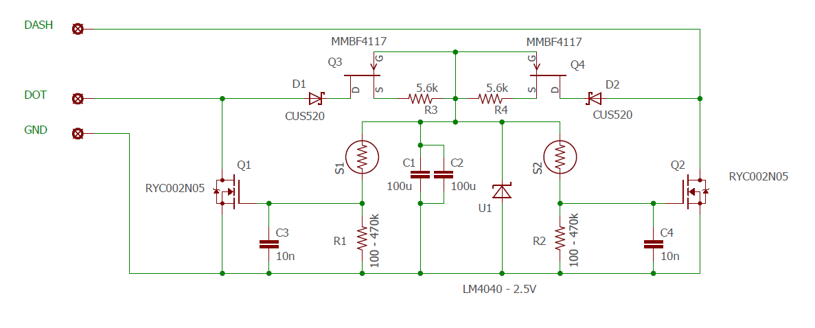
The capacitor sizing is determined by the fact that it is the only source of power when both paddles are activated simultaneously (iambic sending.) In this case, both lines are grounded and hence no current flows to the capacitor. When only one paddle is activated, the capacitor is replenished by the other paddle line. The period over which the voltage on the transistor gate is held high enough to maintain it active is determined by the charge level on the capacitor and the total resistance of the divider network. The latter is determined by the resistor (R1/R2) and the pressure applied to the pressure sensor – hence quite variable.
The R1/R2 sets the sensitivity of the paddle with higher values leading to higher sensitivity. In practice, I’ve found that setting it to anything between 100k and 470k seems to work fine.
One of the most complex elements of this design is scavenging enough current to keep the capacitor charged without dropping the key line voltage below the “high” threshold of the key line sense port. This is typically a minimum of 75% of Vcc. This sets the maximum current that is practically drawable to about 82uA for a 10k pull up resistor to 3.3V. This current limit could be achieved using a resistor, but this would have the negative effect of slowing the capacitor charge significantly. A better (albeit more complex) solution is to use a current source.
I’ve implemented the current source using a well known JFET current limiter in series with a Schotkky diode to prevent back-flow of current when the key line is active. There is some significant variability in the limited current due to a wide tolerance in the JFET parameters, so there may be a few cases where the value of the resistor will need adjustment for reliable operation.
In this design, the current source is set to around 82uA which covers the worst case of 10k pull up and 3.3V supply. Theoretically, with a 50k pullup, there simply isn’t enough current available to charge the capacitor faster than the sensor depletes it. However, in practice, I’ve found that the key seems to work fine with such rigs (tested on KD1JV MTR 2 and KD1JV Soda Pop). For rigs with higher than 10k pull ups, it may be necessary to modify them to add 10k pull up resistors on each paddle line to the appropriate supply line (the one feeding the microcontroller that terminates the paddle lines) to achieve reliable operation. This is very unlikely to cause any problems with the rig.
The MOSFETs chosen for this application were selected based on the low threshold voltage (about 0.5V at 330uA drain current). The low threshold voltage means that the circuit will work down to the low 2.5V regulated supply voltage.
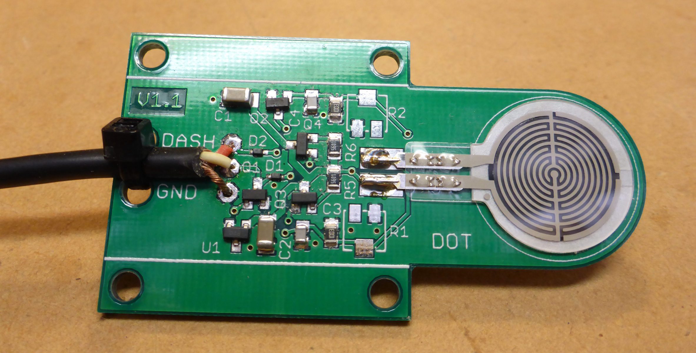
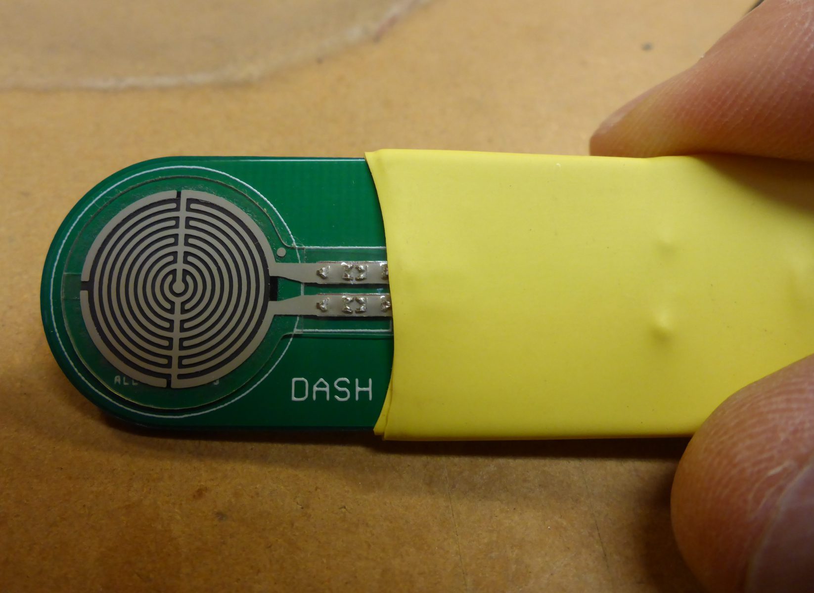
The PCB is designed to allow a couple of mounting options. There are 4 screw holes in flanges that can be used to attach the board to some sort of package or support such as a piece of wood or plastic to provide a grip or mounting. Alternatively, the side flanges can be cut off and the remaining PCB encased in heat shrink tubing to provide a minimalist paddle. Note that there are now also PCB gerbers for a paddle with or without mounting flanges (see below).
The PCB is designed to have a 3 core cable attached directly and held in place by a small cable tie through the provided holes.
The whole paddle and cable weighs in at just 26g, so is probably about as light as you can get for a portable CW paddle.
I have provided build data below if anyone wants to try it out.
Appendix – Build data
PCB gerber files:
There are three versions of the PCB available. There are versions with and without the mounting flanges and also a longer version without mounting flanges for those with larger hands.
Here are the links to the gerber files:
- V1.2 – Standard with mounting flanges
- V1.2A – Standard length with no mounting flanges
- V1.2B – 100mm long with no mounting flanges
For PCB manufacture I use AllPCB.com which will produce 5 of these boards for US$5 plus shipping – they are located in China and provide fast turn around and excellent quality in my experience. Note that when ordering, the board sizes are:
- V1.2: 34 x 63mm
- V1.2A: 22 x 63mm
- V1.2B: 22 x 100mm
Bill of materials:
The following table contains all the components together with stock numbers for Digikey.
| Part | Qty | Value | Case | Desription | Manufacturer | Manufacturer part no. | Digikey number |
|---|---|---|---|---|---|---|---|
| Q1,Q2 | 2 | SOT23 | N-Channel MOSFET, 300 mA, 20 V, | Rohm | RYC002N05T316 | RYC002N05T316CT-ND | |
| U1 | 1 | SOT23 | 2.5V voltage reference | TI | LM4040CEM3-2.5/NOPB | LM4040CEM3-2.5/NOPBCT-ND | |
| C1,C2 | 2 | 100u | 1206 | Ceramic X5R capacitor | Murata | GRM31CR60J107ME39K | 490-7217-1-ND |
| C3,C4 | 2 | 10n | 805 | Ceramic NPO capacitors | Murata | GCM2195C1H103JA16D | 490-4783-1-ND |
| R1,R2 | 2 | 100k | 805 | 1% resistor | TE Connectivity | CRG0805F100K | A106052CT-ND |
| Q3,Q4 | 2 | SOT23 | JFET N-CH 40V 0.225W SOT23 | ON Semi | MMBF4117 | MMBF4117CT-ND | |
| D1,D2 | 2 | SOD323 | Diode Schottky 30V 200mA Surface Mount USC | Toshiba | CUS520,H3F | CUS520H3FCT-ND | |
| R3,R4 | 2 | 5.6k | 805 | 1% resistor | Vishay | CRCW08055K60FKEA | 541-5.60KCCT-ND |
| S1,S2 | 2 | Force sensor | DFRobot | RP-C18.3-ST | 1738-SEN0294-ND |
Pressure sensors:
The sensors used in this project are now available from Digikey, but may also be found on Amazon, Aliexpress and Ebay. I suggest you Google: RP-C18.3-ST
Construction hints:
- All components are located on one side of the board except for the dash pressure sensor
- Here is a link to the component overlay that will help with component placement – Overlay
- Suggest fitting the surface mount components first using solder paste, a hot plate and hot air gun – the component order is not important
- Fit the sensors last – they usually have adhesive already on the sensor covered by a protective paper. Remove the protective paper and align them carefully to each side of the board with the contacts centred on the corresponding pads and solder.
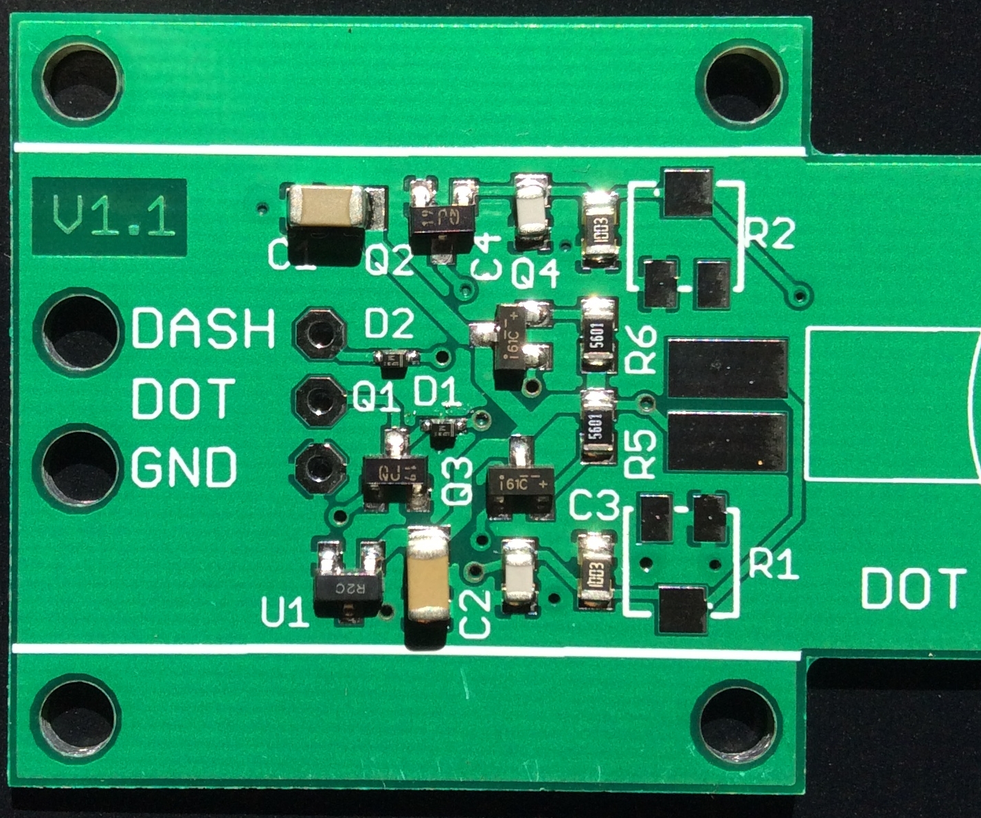
- Here’s a closeup of the assembled board (this is version 1.1 without trimpots or sensors) courtesy Jerry AA1OF which may help with parts placement and orientation:
Hi David,
Thanks for your generosity in sharing your genius.
I followed and built your HWEF and matching box and that is working well for parks and peaks.
So now I look forward to another project of yours to dissect and build.
Thanks for your inspiration and elmering.
Regards John vk5flea
Thanks John, good luck with it and happy to answer questions if you run into any difficulties.
David, you have missed your calling, I think you should be working for Elecraft.
Thanks Paul – it’s quite a big step from a pressure paddle to a K3s!
I second this. Elecraft. Or building and selling this online for those of us who don’t have the eyes or skills to put this together but would definitely use it in the field. Adam W7MP
Hi Adam,
Thanks for your interest. Unfortunately I don’t have time to build or even produce kits due to family commitments and a demanding day job. Probably the best option is to ask around other amateurs who may be interested and have the skills and then do a group build. Or you could also try and convince one of the innovative ham manufacturers to pick it up!
73
David
VK3IL
Hey David, New update. My Sota mate George WB5USB and I had some of your boards made up. Got mine up and working first time. That was even after I installed D2 backwards ….and I had even checked it with an Ohm meter before. Good thing I checked it again after installed. I could not see the cathode stripe on mine so I had to rely on the meter. I swapped out one of my battery operated keyers with your board. Anyway will let you know how I or we make out on the next SOTA activation. BTW it works very well with the KX2 and KX3. Thanks for the help and all the circuit board Info.
73’s
Tim – K5DEZ
73’s
Tim – K5DEZ
Hi Tim,
Great to hear! Will be very interested to hear how it goes on SOTA activations. It needs a good bit of field use to find its limitations. The two things that need verifying is its immunity to RFI in a range of field conditions and also how well it works for higher speed operators than me (I can only really operate at about 12 WPM). I suspect there will be a speed beyond which the pressure sensors may not keep up practically.
73 David VK3IL
I have not doubt it will not be bothered by RFI in any way. On the summits with the very familiar reports/chatter I am usually a 18-20wpm guy. I will also see if I can get a couple more of the 25wpm SOTA guys to give it a good work out to see what they think. I’m sure they will like it too. Well let you know.
Tim K5DEZ
BTW….On my circuits and your circuit boards I used a 470K fixed resistor. The sensitivity is very good.
Tim K5DEZ
OK, good to know. I’ll keep this in mind if I find it not sensitive enough.
David VK3IL
Update….used your circuit board in my “Version 3” paddle on a SOTA summit. As predicted it worked flawlessly…..except when I messed up. Since the sota exchanges are so short an predictable it worked very well for me at my 20wpm limit. My mate George WB5USB is working on his now but with a twist. His will use the keyer paddles to push on the sensors with a tiny rubber or firm foam pad so it will resemble a typical “normal” keyer. I’ll get some pictures for you when he completes it.
Tim K5DEZ
Great to hear Tim. George’s build sounds interesting, would certainly like to see pictures when it’s done.
73 David VK3IL
I’ve discovered that the MMBF4118 part used for Q3 and Q4 has been discontinued. I’m searching for a suitable replacement, but I’m not quite sure about the important specs. Any suggestions?
Thanks.
Ken KJ7JPX
Hi Ken,
Yes, JFETs are getting harder to find these days. Having a look at what’s available at Digikey, I think the best substitute would be the MMBF4117 which still appears to be active: https://www.digikey.com.au/product-detail/en/on-semiconductor/MMBF4117/MMBF4117CT-ND/3042811
It’s specs are close enough that it should work fine. But please let me know how it goes and I will update the BOM if you find it works well.
Regards,
David
VK3IL
Thanks! Not long after I posted, I found the MMBF4117 on DigiKey’s website. It was on the datasheet so I guess I should have found it sooner. I’ll certainly let you know how it goes with those. I’ve got the sensors and some boards already ordered, just need to get the rest of the parts.
Ken
KJ7JPX
Does anyone have an extra PCB they would like to sell?
Pse contact me. Email address good on qrz.com
Tnx de Arnie W8DU
Hi Arnie,
You might be waiting a fair while to get a response here. I’d suggest also asking on any forum where you’ve seen the paddle mentioned.
73
David
VK3IL
Finally got around to putting this together. I was procrastingaly having the deal with the SMD items. Well, it worked first time. Thanks again. It did make a 3d-printed holder for the paddle and it makes the ergonomics more friendly.
Not sure how to post a photo here, but it was a pretty simple design. I did use epoxy to seal the SMD’s instead of heat shrink. Tnx fer this design!
73 de Arnie W8DU
Hi Arnie,
I’m glad it’s working for you. The 3D printed holder is a great idea. If you have that publicly available somewhere, I’m happy to add a link to it to the article.
73
David VK3IL
I just finished one of your V2 pressure sensor paddles. It is intended to be used with one of my QCX mini transceivers. Before testing the paddle on this radio, I have checked the keying voltage to be less than the upper limit you have recommended.
After soldering (I am an SMD newbee because of my bad eyesight) I did a test and it worked as it should, both sides, dash and dot.
I want to recommend a more sturdy and much more slim kind of attaching the cable mechanically to the printed circuit board (PCB) than using a cable ty.
I use a thin woven rope, like a fly fishing line or these robust thin woven ropes used for venetian shutters. I have wound such a rope four or five times around the calbe and always fed it trough the holes in the PCB. All windings lie neatly one by one on the cable and on the PCB. Then I pulled both ends tight and made a simple double knot. Finally I secured both sides, the cable side and the PCB side with two drops of cyanacrylate glue (“Super glue”). This holds the cable much better attached to the PCB and is less bulky than a cable ty.
Hi Andy,
Thanks for the great tip! If you have a close up photo you’re willing to share, I’ll add it to the article so others can use this method too.
73 David VK3IL