
The first version of my Pressure paddle (written up here) was released in early 2019. In using this version I noticed something interesting – holding both paddles continuously (iambic sending) kept working indefinitely, even though the storage capacitor would discharge and they should have stopped after around 5 seconds. This caused me to examine this further and I came to the realisation that the paddle could be greatly simplified.
There is an interesting property of MOSFETs: if the gate and drain of an enhancement mode mosfet are connected together, then the voltage across the drain-source junction will equilibrate to the threshold voltage at the current being passed through the device.
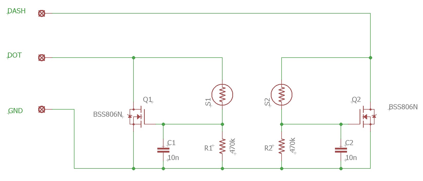
This mechanism allows an extremely simple circuit to be created to achieve reliable switching of key lines. Here’s the new schematic:
How does it work?
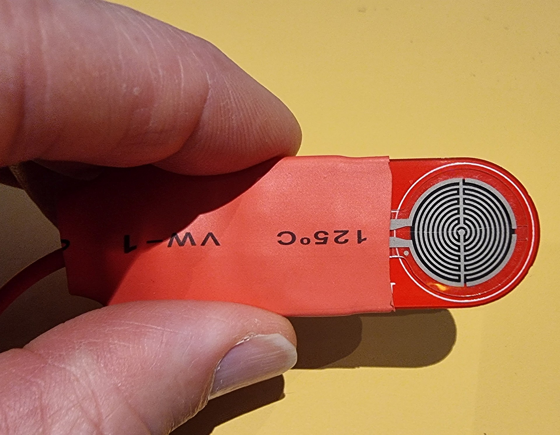
In this circuit, S1/S2 are the pressure sensors as used in the original design. They have an extremely non-linear pressure-resistance characteristics. With no pressure, their resistance is > 10 Mohms. With even light pressure, the resistance reduces to less than 20 kohm.
If we look at the non-activated state, the sensor is essentially an open circuit and the gate of the mosfet will be pulled to ground through R1/R2, switching off the mosfet and the key line will float high by the action of the pull-up resistors inside the transceiver.
When the sensor is lightly pressed, the resistance drops to say 20 kohms. This will raise the gate voltage of the mosfet to greater than 95% of the drain voltage forcing the mosfet to conduct. As the mosfet switches on, the decreasing resistance of the mosfet will drop the drain voltage towards zero. However, as it reaches the threshold voltage of the mosfet, the resistance will start to rise until an equilibrium is reached close to the mosfet threshold voltage. As long as this equilibrium voltage is below the Low threshold of the key sense line, then it will be “read” by the microprocessor as key down.
Most processors operate between 3 and 5V Vdd and for CMOS logic, the low threshold is typically 1/3 of Vdd. Taking the worst case of 3V logic, we need a mosfet threshold voltage of below 1V for reliable operation. The chosen mosfet (BSS806N) has a threshold voltage of 0.5-0.9V which is low enough to operate reliably with 3V logic. Note that there are many similar mosfets that would work just as well (e.g RYC002N05, DMN2024U, etc.)
It is interesting to note that the operation of this circuit is almost independent of the size of the pull-up resistor used for the key lines. I’ve tested it with values between 4.7k and 100k with voltages between 3 and 5 volts and it works reliably for all. However, do not try and use this for vintage rigs with high voltages on the key line. 6V is the maximum key line voltage that this design is specified for.
The only other component in the circuit is C1/C2 which is there to bypass any RF that may find its way to the gate of the mosfet. This capacitor combined with R1/R2 sets the release time of the circuit to around 170us which is short enough not to be a problem at even high keying speeds.
Rig compatability
To date, experience is that this paddle works with most modern transceivers. The only ones that have had issues is where there are large resistors in series with the key lines which prevent the paddle pulling the logic input low enough to trigger it. Some rigs also have protection diodes in series (for example the IC705) which make operation marginal.
If you have a rig with series components and are happy to void any warranty on the rig, it is usually possible to modify the series components to make them work.
If a rig has a large series resistor (these are usually there with a capacitor to form a low pass filter to reduce the chance of RF triggering the keying circuit), try reducing the value of the resistor to around 220 ohms or less. You could also change the resistor to a small inductor or ferrite bead.
If the rig has a protection diode, you could simply bypass it, but of course you would then not have the protection on the input!
Construction
Similar to the first version, I’ve designed two versions of the PCB to accomodate individual preferences as to board length. Due to the many fewer components in this design, I have been able to include mounting holes without the need for separate mounting flanges for anyone who wants to attach it to something.
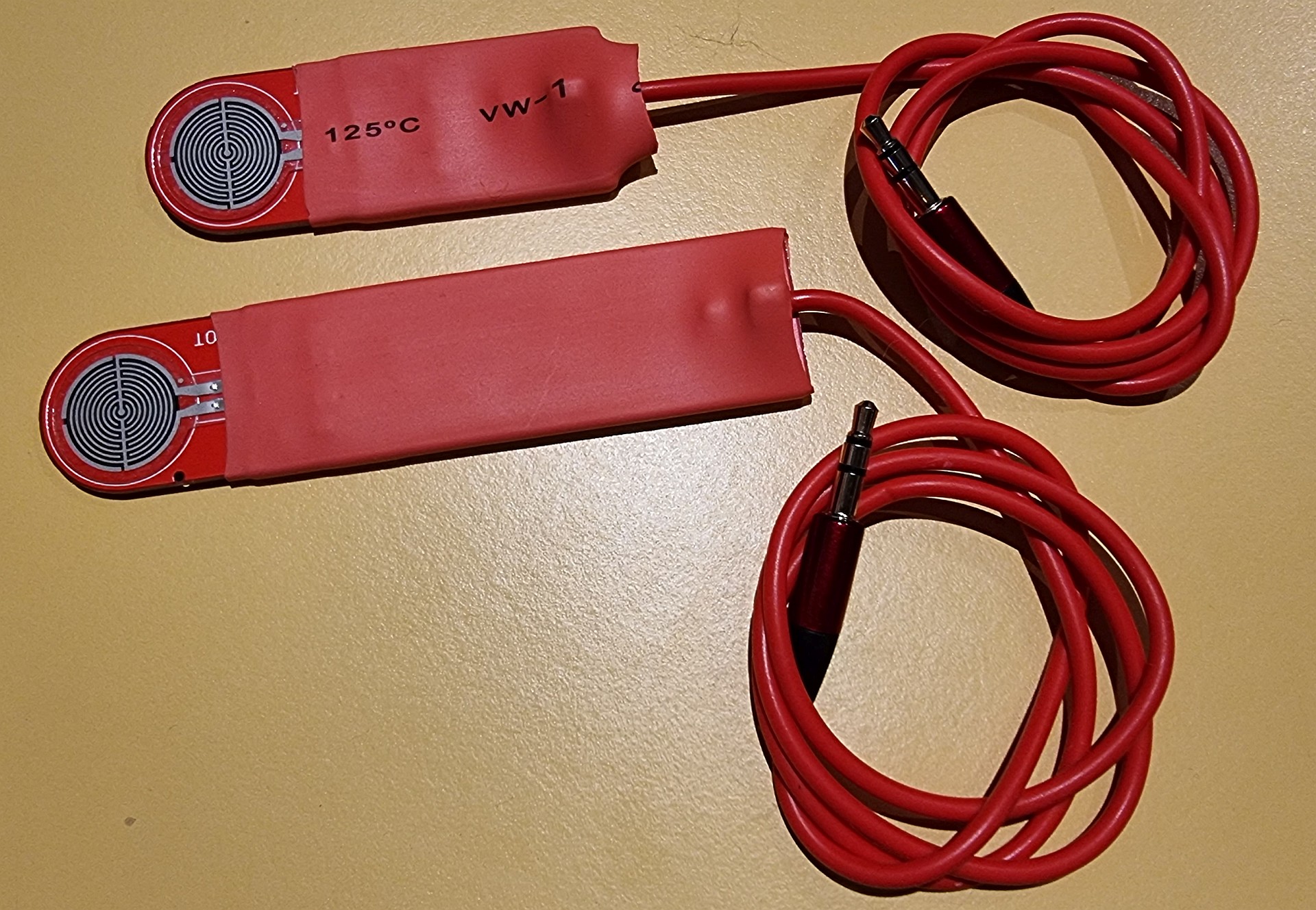
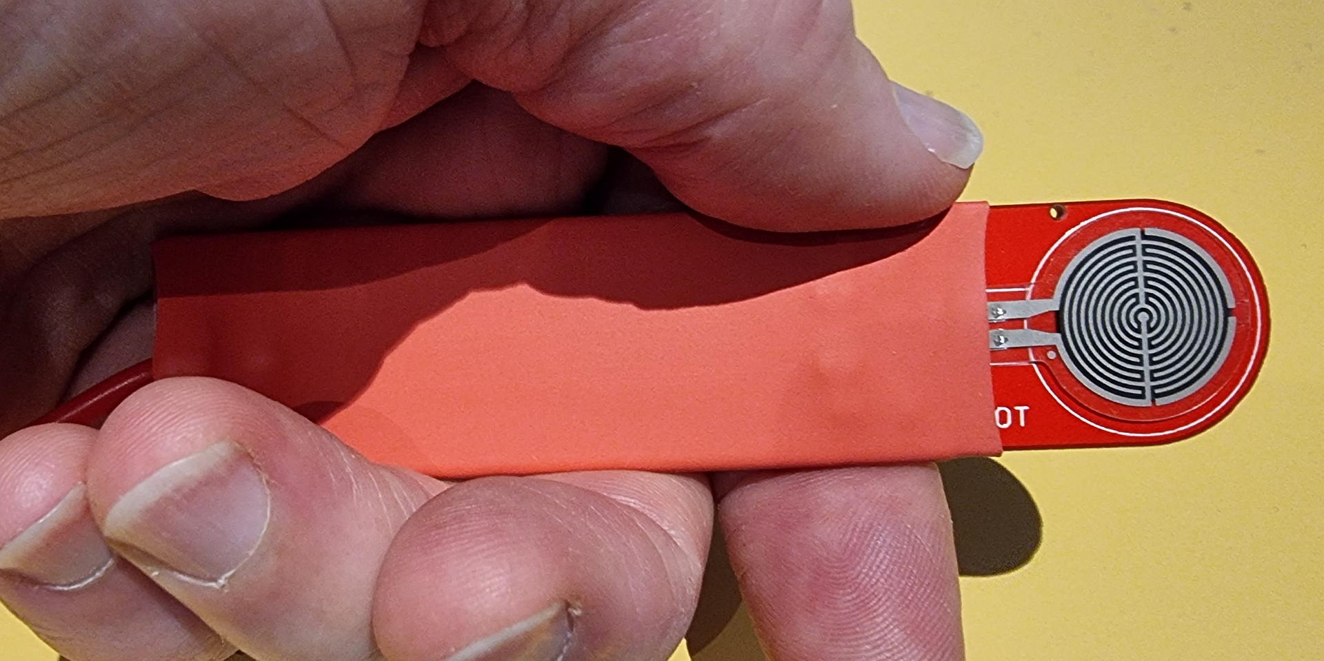
As previously, the simplest packaging is to simply use a couple of layers of heat shrink tubing to protect the components and provide a grip. If you prefer something a little more substantial, you can either mount the board to a wood or plastic carrier of some type, or sandwich the boad between two pieces of closed cell foam and hold it together with heatshrink. Have a look at VK3PF’s blog to see this style of packaging.
The PCB is designed to have a 3 core cable attached directly and held in place by a small cable tie through the provided holes.
Another way to attach the cord is to use some thin braided cord such as that used in modern window blinds or fishing braid. Below is a photo from a contributor, Andy, who has used this approach to make a neat termination.
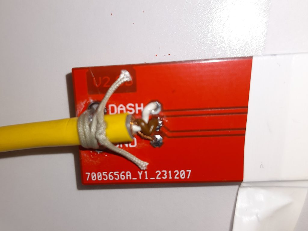
The whole paddle and cable weighs in at just 14g (small) and 19g (large), so is probably about as light as you can get for a portable CW paddle.
I have provided build data below if anyone wants to try it out.
Update Sep 2024
This project has been gaining significant traction amongst amateurs in the last couple of years. There are now two sources to purchase kits and the second one also provides a completed paddle for an additional fee. Here are links to the two sites if you would prefer to obtain a complete kit:
FunkAmateur online shop (in German – use Google translate)
There is now also a complete paddle availble from Vince VE6LK at his shop:
There are also now a couple of YouTube videos that demonstrate construction of the paddle which may be of assistance in tackling the build.
My thanks to those amateurs who are providing support for this project.
Appendix – Build data
PCB gerber files:
There are two versions of the PCB available. There are two lengths available: 63mm and 100mm. Both are 22mm wide.
Here are the links to the gerber files:
For PCB manufacture I use AllPCB.com or JLC PCB which will both produce 5 of these boards for less than US$5 plus shipping – they are located in China and provide fast turn around and excellent quality in my experience. Note that when ordering, the board sizes are:
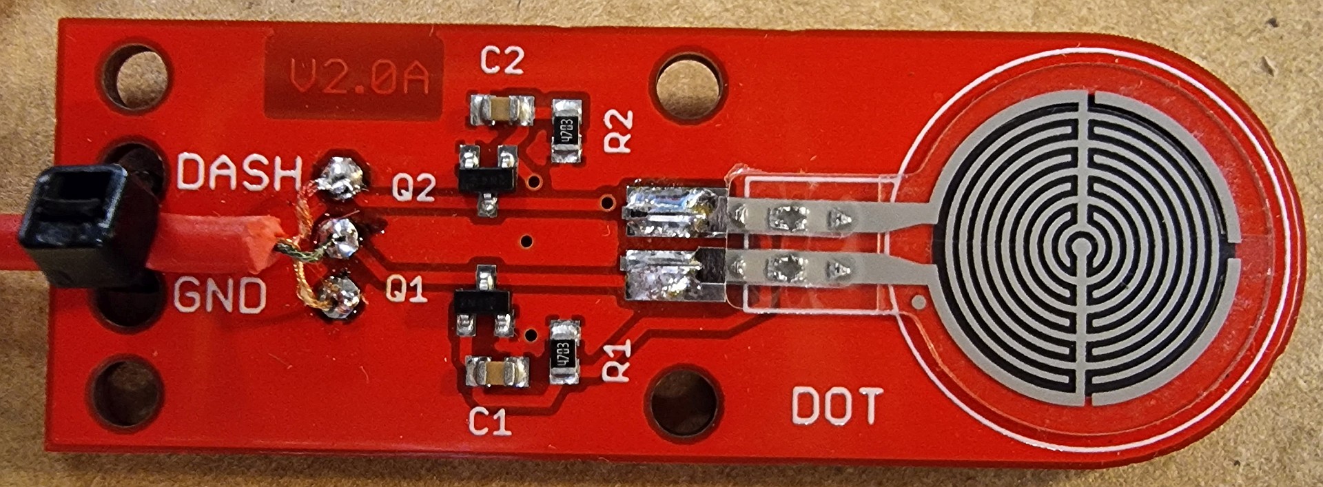
- V2.0A: 22 x 63mm
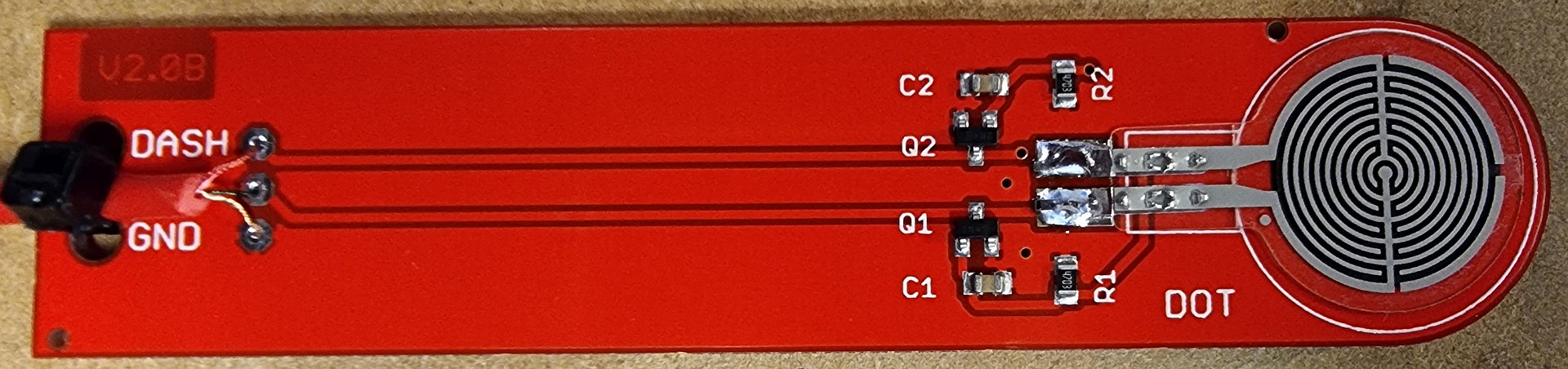
- V2.0B: 22 x 100mm
For North American readers, the cheapest option is probably OshPark due to their free shipping. I’ve uploaded the files there and you can order them using the following links:
Bill of materials:
The following table contains all the components together with stock numbers for Digikey. Note that if stock shortages result in some components being temporarily unavailable, it is fine to substitute components with similar specifications. As noted above, the key specification for the MOSFETs is the threshold voltage which should be below 1V.
| Part | Qty | Value | Case | Desription | Manufacturer | Manufacturer part no. | Digikey number |
|---|---|---|---|---|---|---|---|
| Q1,Q2 | 2 | SOT23 | N-Channel MOSFET, 20 V | Infineon | BSS806N | BSS806NH6327XTSA1CT-ND | |
| C1,C2 | 2 | 10n | 805 | Ceramic NPO capacitors | Würth Elektronik | 885012007009 | 732-7579-1-ND |
| R1,R2 | 2 | 470k | 805 | 1% resistor | Yageo | RC0805FR-07470KL | 311-470KCRCT-ND |
| S1,S2 | 2 | Force sensor | DFRobot | RP-C18.3-ST | 1738-SEN0294-ND |
Pressure sensors:
The sensors used in this project are now available from Digikey, but may also be found on Amazon, Aliexpress and Ebay. I suggest you Google: RP-C18.3-ST
Construction hints:
- All components are located on one side of the board except for the dash pressure sensor
- The component placement is clearly marked on the PCB, so placing components should be straight forward
- Suggest fitting the surface mount components first using solder paste, a hot plate and hot air gun – the component order is not important
- Given the simplicity of this board, you should be able to successfully build it with a fine tipped soldering iron by tinning one pad of a component, placing it and re-melting the solder, then soldering the remaining pins
- Before you fit the pressure sensors, check their resistance with no pressure applied. It should be very high (>10 Mohm). I have occasionally come across faulty sensors with much lower resistance.
- Fit the sensors – they have adhesive already on the sensor covered by a protective paper. Remove the protective paper and align them carefully to each side of the board with the contacts centred on the corresponding pads and solder.
- Attach the cable last with whatever plug your transceiver requires. Hold the cable in place with a small cable tie (zip tie) through the holes provided
Hi David, compared to V1 what parts can be used for V2. I have V1 but have not built it yet as I do not have the hand skills and eyesight now a days to work on this project. I also don’t know anything about using soldering paste. Consequently I have this project sitting in the filing cabinet awaiting for someone to help me build it or on sell it. I would like to build the V2 though, with assistance.
Look forward to hearing from you soon.
73 de Geoff
Hi Geoff,
If you have a V1 kit, you should be able to re-use R1/R2, C3/C4, Q1/Q2 and of course the pressure sensors. Note that R1/R2 in the V1 kit are 100k, ideally you want to replace these with 470k resistors, but it is quite likely to work with the 100k values depending on the rig you are trying to use it with. You can also reuse the PCB by populating the aforementioned components only and making one track cut and adding two jumper wires. Here a a couple of links that should help if you want to re-use the V1 PCB.
PCB modifications
Component overlay
The first file shows a red line where the track needs to be cut and two blue lines where jumper wires need to be added.
The second file has a red line through the components that are not needed for a V2 build.
I hope this helps.
73
David
VK3IL
Thanks David, a great help. I now have some direction. Want to use it with IC7000, FT-891 and a TS-990s
73 de Geoff
Hi David,
Does your paddle key work with Yaseu 817 radio?
Thanks,
Robbie
Hi Robbie,
I don’t have a 817, but looking at the schematic, the 817 uses a 10k pull-up to 5V, so yes, it should work fine.
73
David
VK3IL
Thanks David. Great work. I bought the earlier version as a kit from Peter VK3PF, which was excellent.
Used your gerber files to order boards for v2 and again excellent results.
Works very well with my FT817, IC7200 in fact all of my rigs including uBitx.
Appreciate you sharing your work.
Best
Ian VK5IS
Hi Ian,
Great to hear it’s working for you! Thanks also for confirming it has worked with those rigs too.
73 David VK3IL
Having a lot of trouble finding the mosfet anywhere apart from digikey – who are having trouble with delivery times. I can find all other parts locally.. Any tips on finding a similar / replacement mosfet?
Hi Scott,
Yes, the current parts shortage is a problem. There are quite a few possible substitutes for this that would work. The main specification you need to look at is the Vgsth which needs to be less than 1V. Apart from that, any N-channel MOSFET in a SOT23-3 case with the same pinout should work. A quick search of Digikey shows about 15 options in stock. Here are some possible numbers: ZXMN2A01FTA, SI2302CDS-T1-GE3, BSR802NL6327HTSA1, TSM250N02CX, NXV40UNR, SI2300-TP, SI2314EDS-T1-E3, G6N02L, BSH105,215, NXV55UNR, SI2312BDS-T1-GE3, TSM210N02CX, TSM320N03CX. Note that you should check the footprints before ordering. I obviously haven’t tested these, but on paper they should work. If you get one or more of these and they test out OK, let me know and I’ll add it to the article for other’s benefit.
73,
David
VK3IL
Thanks David.
I hunted around for a while but could not find replacements in Australia. Eventually my parts from Digikey arrived, I have built a key and it works perfectly. Thanks so much for this generous design. It’s great.
cheers..
Scott VK4MGL
Glad to hear it’s working Scott.
73
David
Awesome job and thank you so much for sharing the design and all your hard work that went into creating the gerber files.
Just received my boards from JLC and made up my paddle and it works remarkably well.
I do wonder how you managed to get that heatshrink applied without delaminating the force sensors?!! I guess you have to be very careful applying the heat.
Hi Michael,
No problems, I’m glad it’s working well for you. In terms of shrinking the heatshrink, yes, you need to be careful. For mine, I held the paddle with my fingers over the sensors and then carefully directed the hot air to avoid burning my fingers! You could also potentially use a large pair of pliers to cover the sensors (gently).
73
David
VK3IL
This looks like a fantastic little key. I just placed the order for 3 boards and parts to construct all three. Have you considered modifying the board to accept a 3.5mm jack that can be soldered directly to the board to accept a male 3.5mm plug? Just wondering if there was a particular design choice with the route you took here (not saying one method is better than the other, just curious for my own edification). Thanks for making this available to everyone!
Hi Gus,
Thanks for your interest in the project. Yes, I considered adding a 3.5mm jack, however decided against it in the interests of weight and compactness. It would have created a large lump on an otherwise compact PCB. I decided that a simple direct cable connection would be neater and potentially more durable. There’s also the issue that there are a myriad of 3.5mm jacks, all with different footprints – designing for one of them would also have potentially created parts sourcing issues if it went out of stock (as many parts are at present due to supply chain issues).
I hope it works well for you.
73
David VK3IL
Thank you so much for your designs. I just recently assembled a V1 of this, not having seen the mods to use the V1 board for a V2 design. I have more boards and will try that next. In any event, I did make a 3d-printed little base that is held between the thumb and index finger of the opposite hand. There is a slot that the V1 board (and I assume the V2 board) fits into and is secured with 2 M3 screws. I printed it in red, to match the color of my V1 board. I did mount a 3.5mm jack that I connect to with the keyer 3-conductor cable (I use a stereo audio cable) and it works great. If I could figure how to, I would post a pix of it here.
Tnx es 73 de Arnie W8DU
Hi Arnie,
Glad it’s working well for you. If you load up the 3D printed base to https://www.thingiverse.com/ (or similar site), I can add a link to it to the article for others who may be interested.
73 David VK3IL
Do you sell already built units? I’m not a builder and would like to purchase one for my POTA/SOTA adventures with my Icom IC-705.
tnx es 72 de AI3W, Rick
Hi Rick,
Thanks for your interest. Unfortunately I’m not in a position to provide these units (or even kits) which is why I’ve published all the details for others to build. It may be worth asking around to see if anyone (or perhaps a club) would like to do a build and make one for you.
73 David VK3IL
Well I’ll be darned — it works! This is my very first SMD project. Fortunately I bought ten of everything and sure enough a few went flying off where ever SMD parts go to die. But with a good magnifier and patience it worked the very first time I tried, no rework required. And works well — this is great little paddle. I would never have tried it if you hadn’t uploaded the boards to OSHPark which made that part of the project trivial. So many many thanks for posting and it’s another key for my station. Very 73, Elwood, WB0OEW.
Hi Elwood,
I’m pleased that is worked for you first time – working with SMD takes some getting used to, but with a good magnifier and some hot air it’s not too hard.
73
David VK3IL
I made two, including 1/8″ TRS plug on 20″ shielded cable. Fully tested. I also have all parts for a third except the pressure sensors. If anyone wants any of this feel free to contact me directly at ecdowney@clearskyinstitute.com. 73, Elwood, WB0OEW.
This week I built two of these pressure sensitive CW paddles and they work really reallly well; exceeded expectations. I very much prefer using this over my CW Morse portable paddle. The VK3IL paddle is making a great companion to my QCX-mini transceivers.
This was my first surface mount device project. The tiny size of the components was initially intimidating. But through watching a few Youtube instructional videos on SMD soldering, using my cell phone held on a stand for 10X magnification, and with the pre-made PCBs from Oshpark, construction turned out to be trivial.
But wow do they work well. They never miss a dit or a dah. The pressure required is light, just a bit more than a touch. Response if very fast and positive. Components and PCB board were readily available and arrived quicklly. Total cost was minimal.
Thank-you VK3IL for sharing your work on this design. What a generous and fun contribution to the hobby..
Hi William,
Thanks for your interest in the project. Yes, SMD soldering can appear intimidating at first, but once you are setup for it, I find it actually easier and quicker than through hole.
I’m pleased it’s working well for you.
73 David VK3IL
Measuring the pressure required to activate each of the two VK3IL pressure paddles I recently constructed I find that:
the first paddle activates on both sides at a bit less than 15 grams
the second paddle activates with 20 grams on one side and 23 grams on the other.
Both paddles feel light in their action and very uniform in their response. I slightly prefer the feel of the 1st one that responds at 15 grams.
I hope these pressure measurements are helpful to others as they contemplate constructing a VK3IL paddle.
Thanks again to David VK3IL for a nice project design.
73 Bill AE0SU
Thanks for the kind words and interesting measurements Bill. Yes, it’s certainly quite light pressure needed which makes it quite responsive. It’s possible to adjust the required pressure somewhat by changing the value of the resistors R1/R2. Reducing their value will decrease sensitivity.
73 David VK3IL
I ordered the boards from Osk Park, got three boards for $17.00 Problem is the dot’s work, the dash’s do not. On all three boards, the dash’s don’t work. I’m really bumbed. Was so looking forward to these.
Hi Keith,
Sorry to hear you are having issues. That’s an unusual problem, but most likely solvable. I presume you’ve done the usual checks such as confirming component types and orientations and checking the soldering. The fact that the same issue appears on three separate boards tends to suggest it’s something to do with the radio rather than the boards themselves. What radio are you using it with? Do you have a different radio you can test with? To diagnose further, I would suggest measuring the voltage on the dot and dash key lines both with the pressure sensor pressed and not pressed. I’m guessing it may be an issue with a large value series input resistor not letting the dash line logic input drop to an adequately low voltage.
I’ll reach out to you directly so we can try and work through the problem.
73 David VK3IL
Hi again David,
After a few years of using these keys in the bush with great success, I have built another one for a friend, but we can’t get it to work with a Yaesu FT100. It tests fine on my rigs but is there something about these older rigs that won’t work or needs adjusting?
Hi Scott,
Do you have a schematic diagram for the FT100? I’d need to have a look at the key input circuit to see if there’s something unusual. Some rigs have reasonably large series resistors as part of their RF interference mitigation (I think the FT2000 was one of these) and this causes an issue as the voltage at the sensing point does not drop low enough.
73 David VK3IL
Hi David,
just built a couple of your paddles. Thank you for sharing this so widely! Brilliant concept and works so reliably even above 20wpm. Hard to make a paddle simpler or lighter!
73 Peter HB9EBE
Thanks Peter,
I’m pleased you are enjoying the project!
73 David VK3IL
Hi, build one of thee. On IC-705 it doesn’t work, the voltage is 3.3V .. 1V. On (tr)uSDX it works fine as I think it has 5V pull up, didn’t measure.
Any ideas could this be fixed to work on 705? A bit of pull down?
Hi Jouni,
OK, it sounds like the 705 has a very low threshold for their input logic. The specification is that 3.3V logic must register a low state with any input up to 0.8V and register high for voltages abouve 2.0V. Most devices have their switching threshold around 1.5V with some hysteresis. From your note, I take it that you are measuring 1.0V on the key line with a paddle pressed. The voltage here will be a function of the size of the pull-up resistor in the rig (smaller value of pull-up the more current and hence higher the voltage), and also the ambient temperature (the lower the temperature, the higher the voltage). The value of 1.0V is of course 0.2V above the low specification for 3.3V logic, so it is going to be marginal and if your rig happens to have a fairly low threshold, then this would explain why it doesn’t work.
Adding a pull-down resistor may be worth a try, but it may need to be such a small value to make a difference that it would stop the keyline then reaching the upper 2V threshold. You could also explore other mosfets, but there are not many that have a lower VGS(th). Perhaps try a STR2N2VH5?
Failing these, the other approach would be to build up a V1 version of the paddle as this switches the mosfet hard on and should work reliably.
Addendum: I found the schematic of the 705 and discovered that it has a series protection diode in each of the key lines. This adds an estimated 0.32V to the voltage at the key port, so the receiving logic will be seeing around 1.32V when the key is pressed. This is certainly likely to be not recognised as a low condition and would explain the behaviour. This points to another potential fix – bypass the protection diode. I would only attempt this if you are confident with working on complex surface mount gear and happy to void your warranty. If you want to explore this, the relevant parts are D151 and D152, which are dual diodes, and you would need to short pins 2 and 3 on each of them. This would of course remove the protection for positive over voltage on the key lines (which are currently protected up to about 40V). Again, I would not recommend this!
73 David VK3IL
Thanks for such detailed answe David! And I forgot to thank for making this project publicly available.
I’m not going to bypass those diodes for sure, that makes such expensive radio too vulnerable 🙂
Of course solution would be to add some small microcontroller in between, but of course it needs 3.3V or 5V. I don’t want more batteries to charge. Some microcontrollers have really low sleep current consumption so that could be a solution; put the microcontroller to sleep once keying is not used.
Anyways, 73 again and thanks for everything!
Are you using genuine BSS806N transistors? I just built the paddle and it is working well on my IC-705. Both dit and dah sides are working flawlessly.
Is it possible to modify it to have option to set sensors sensitivity?
Hi Stan,
The sensitivity of the circuit is set by the size of R1/R2. If you decrease the value, it will become less sensitive and if you increase the value it will become more sensitive. Note that if the value is increased much higher, it will also affect the release time (making it longer) and hence start to limit the maximum sending speed, however that would only start to become an issue if you increased it to maybe 5 Mohns or higher. In a much earlier version I put a variable resistor in here, but found that it wasn’t really needed. If you want to significantly alter the sensitivity, I’d suggest trying much lower or higher value resistors to find something that meets your preference.
73 David VK3IL
Those pressure sensors are expensive. All they are is a conductive trace on a piece of mylar. Wouldn’t it be easy to design the interlaced spiral into the circuit board itself, increase reliability, save money, and improve build time? The glue on the back of the sensor is a point of failure. Another suggestion would be to go up a size or two with the parts. Make the build easier for the old and the blind. Also what is the point of the “dit/dah” silk screen?
Hi Mike,
Thanks for your interest in the project. In relation to the sensors, they are actually more complicated than you suggest. They are a sandwich of conductors with an insulating material between them. When pressure is applied the resistance of the insulating material is reduced (likely by thinning of the material under pressure). Hence it’s not possible to replace these with conductors on a circuit board.
On the component size, the mosfets are only available in SOT-23 size – whilst you could increase the size of the resistor and capacitor, not sure it would make it much easier to construct in practice as they would still be small enough to require tweezers. It is now possible to buy a pre-assembled paddle on Tindie – see the link at the bottom of the article.
The dot/dash silk screen is simply to help constructors wire up their cable easily. The paddle can of course be turned over to reverse the dot/dash paddles.
73 David VK3IL
Will the paddles work with the Elecraft KH1?
Hi Andrew,
I don’t own a KH1, so haven’t tested them. They do work on other Elecraft rigs (I have a KX2 and KX3), so unless elecraft has completely re-designed the keying interface, I expect it would work. Others may have experience and comment.
73 David VK3IL
Hi David,
great touch sensor paddle project!
I would like to know, if you know, if this paddle will work with Xiegu QRP radios?
Thank you!
Best 73!
LZ3AW
Hi Toti,
Thanks for your interest in the project. I don’t have any Xiegu radios, so I don’t know. There are not many radios that don’t work, so there’s a good chance that it will. The main thing that causes issues is large series resistors or protection diodes in series with the key lines.
73 David VK3IL
David, thank you for your answer!
I’ll send on your email the schematic of Xiegu G90, if you would like to take a look.
Hi David,
Ordered the parts and built 3 paddles and all 3 work well with my IC7300. New at CW and my first paddle after learning on straight key. Love them. Thanks much!
Dudley N4CDH
Hi Dudley,
I’m pleased to hear they are working well for you. Good luck on your CW journey.
73 David VK3IL
Thanks in advance for still answering questions. A lot of people don’t and this is refreshing.
So… I’ve seen dozens upon dozens of references to these paddles. Yet, what I haven’t seen is whether they can be used as a simple cootie / sideswiper. Just wire both dash and dot as a straight key?
73 es TU de N4REE, Bob
Hi Bob,
Yes, I see no reason why this wouldn’t work, but I haven’t tried it myself. As you suggest, wiring both the dot and dash outputs together to the key line should work.
73 David VK3IL
I copied the entire table from the Bill of materials, and I pasted it into chatGPT to convert it to a DigiKey parts list that you can upload!
https://chatgpt.com/share/68150cd9-5834-800e-99c8-1505ec3f0cee
It took me literally 5 minutes to have it completely ordered.
$33 total for 2 assemblies.
$10 bucks for the 3 pcbs = ~$20 a piece SHIPPED!
I just assembled your key using cheap chinese AO3400 transistors. Without your printed circuit board, on a breadboard with holes. 330 kOhm resistor. In parallel to the resistors and capacitors, I installed 10 V zener diodes to protect the transistor gates. The key works perfectly on KX2, IC-705 and FTdx-101. Thank you for a great idea! 73 de UD6ARJ!
Hi Segrus,
I’m glad it’s working for you. Looking at the specs for AO3400 FETs, they look a bit marginal with a wide specification on threshold voltage and I suspect you would need to select samples with Vgs(th) at the low end for reliability. However, the fact that is working is a good sign. I would still recommend using the specified transistors if they are available.
73 David VK3IL
They were just in my drawer. To be honest, I don’t see much point in a very low threshold voltage. It is different at different currents. And here the current is very small. It seems that you shouldn’t scare people so much 🙂 If someone does not work, it is most likely an incorrect installation or a bad flux for soldering. This scheme is critical for such things.
Anyway, thanks again for the device!
I was inspired by your design and have made what I think is an improvement in a couple of ways. Two drawbacks you mentioned were that some transmitters required an unusually low output voltage to assure being seen as a contact closure, and that some transmitters have a higher voltage supply than the BSS806NE that you used will tolerate (+/- 8Vgs). This second issue is improved to +/-20 V with a 2SK3065 which has otherwise similar specs.
The first issue would be solved if VGS were to be kept at a higher threshold voltage to turn the FET on hard. My suggestion is to separate the gates from the drains. and then use two Schottky diodes, one from each keyer connection to a 33uF capacitor to supply gate drive. Whenever either paddle is open, that side easily and quickly recharges the 33uF capacitor. The 33uF capacitor will discharge only when both paddles are pressed at the same time. This of course happens during iambic operation but takes several seconds to deplete the cap to the threshold voltage.
I built such a circuit, and it works well with my QMX.
The disadvantages are that if both paddles are held pressed simultaneously the cap may discharge to the point that closure ends prematurely. This might happen if code is being sent very slowly. A larger capacitor gives correspondingly longer discharge period and would allow very slow code. A second disadvantage is that the transmitter may be briefly keyed when plugging in the key (until the cap charges). A third disadvantage is of course the additional components (2 Schottky diodes, a capacitor, and optionally different FETs) and the additional complexity. All other components are the same.
I made mine on a proto board and made a 3D case to better fit my hand.
Thanks for your interest in this project and thanks for the additional ideas, particularly the reference to the 2SK3065. Looking at it’s data sheet, the Vgs(th) value looks a little high for this application. It only appears to dip below 1V at high temperatures (see fig 5 of the data sheet), so whilst it would likely work for some rigs, I suspect there would be quite a few cases where it wouldn’t. The high Vgs voltage limit is useful though.
On the idea on using storage capacitor, yes, that does work – I tried this method with my earlier pressure paddle (see Pressure paddle ). I’ve found that the current simpler designs works with most rigs and is obviously much simpler, which is why I recommend this one over the older one.