
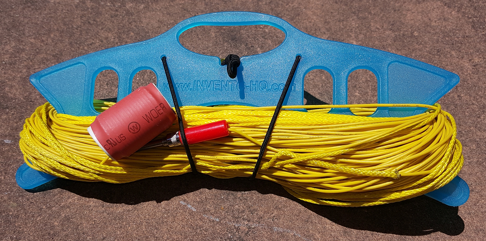
Complete antenna and end lines on a kite winder
I’ve been generally happy with the performance of my 5 band trapped EFHW antenna and have used it on many SOTA activations. However, every time I use it, I have to be quite careful not to break any of the joints to traps or get the traps snagged in trees etc. Consequently, I’ve been looking around for a simpler antenna that will still achieve multi-band coverage.
I came across the following antenna which covers the 80-10m bands with no traps and just one loading coil. It is called the EFHW-8010. It is simply a half wave end-fed on 80m which will resonate on all multiples of that frequency, loaded with a small inductance near the feed end. This inductance has the effect of bring the resonances a bit lower, particularly on the higher bands and thus improving the match.
The commercially available version of this antenna is intended for permanent installation and is way too large and heavy for portable ops. So I decided to model it using 4nec2 and re-design it optimised for portable use. The NEC2 model is in the appendix for anyone who would like to play with it further.
To see the effect of the coil, here are two modeled versions of the same length and same configuration (low inverted-V), the first without any coil and the second with a 4.5uH coil 2m from the feed point:
Wire alone modelled in 4nec2
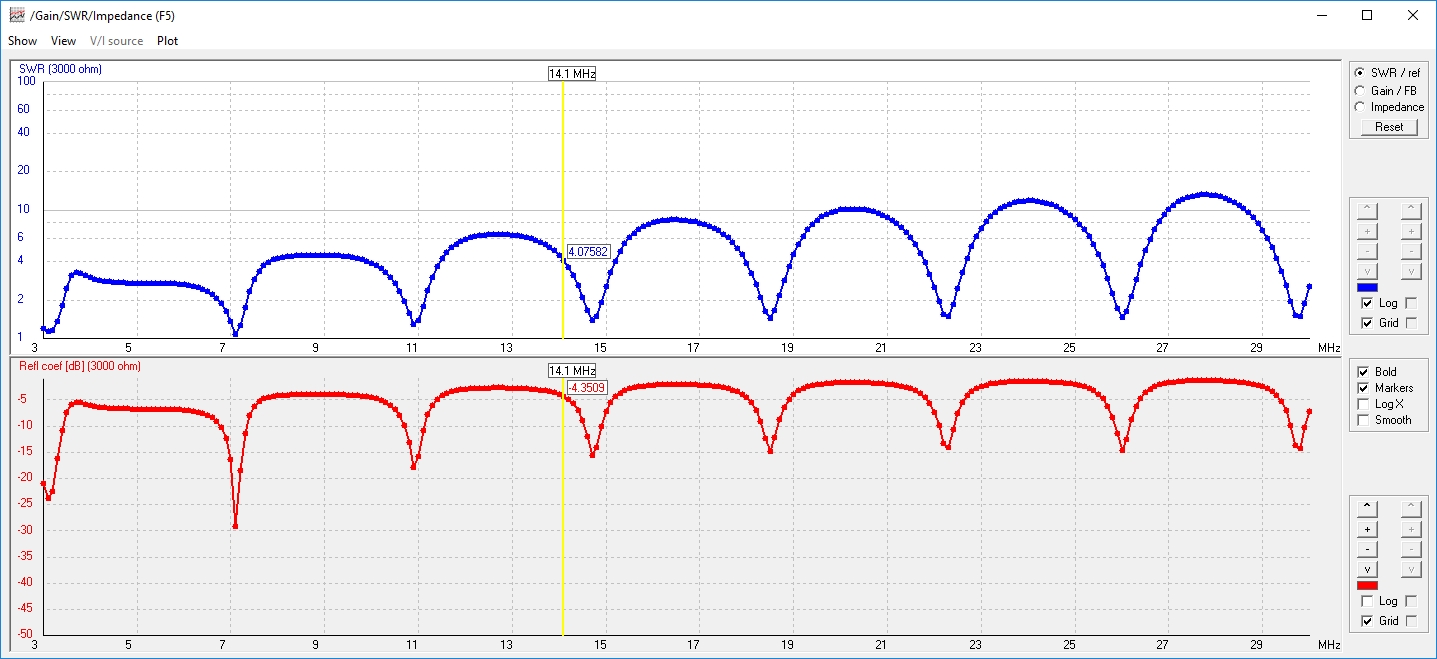
Wire including a 4.5uH coil 2m from the feed point.
You can see that the SWR (measured against a 3000 ohm characteristic impedance to model the feed transformer) dips in the wire with the coil are lower in frequency and generally closer to the amateur bands. Note that the wire was trimmed to be close to 7.0 MHz full wave resonance to give the best result in the lower part of that band.
You’ll see that the SWR is low for the majority of the bands, but is probably not low enough to use without some sort of ATU. However, by getting it reasonably low, there will be little loss on the feed line and the internal ATU on rigs such as the KX2/KX3 will have no trouble matching it. The variable SWR is the trade-off for having a very simple antenna.
The radiation pattern on each band follows the expected shapes for low antennas with increasing length. Here are some sample plots for reference:

Essentially, these are NVIS patterns, becoming slightly more directional on the higher bands.
The construction of this antenna is very straight forward. The wire used was 22 AWG PVC coated hookup wire.
Loading coil detail
The inductor was wound on a 22mm PVC former (a piece of 20mm pipe) with 17 turns of the antenna wire located 2m from the feedpoint. The coil was held in place by drilling two holes in the former about 30mm apart and passing the antenna wire through them from the inside. The whole coil was then covered in heatshrink tubing to hold the turns in place. The final coil measured 4.45uH.
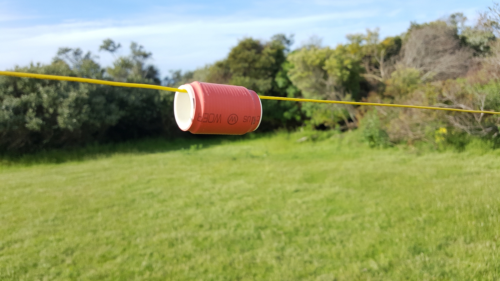
Detail view of loading coil looking back to feed point
The wire was cut to 40m length and then trimmed when set up as an inverted V to minimise the SWR at 7.090 MHz (you could of course optimise for any preferred frequency). In my case, it ended up at 39.21m, but this will vary depending on the specifics of the setup etc.
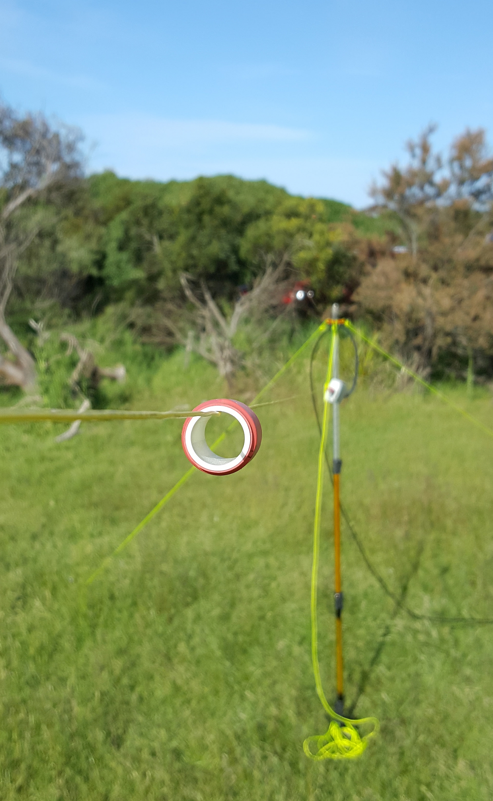
I’ve followed my usual practice of attaching Zing-It line to each end of the wire by feeding the wire into the core of the Zing-It and using Araldite (glue) to secure it in place. This makes it fairly easy to rig in the field in an inverted V or other configuration.
This is an end-fed antenna and hence has a very high feed point impedance that will likely be somewhere between 2000 and 6000 ohms depending on the set up configuration and local ground conditions. I use the same match box that I have used for my other end-fed antennas, the details of which are here.
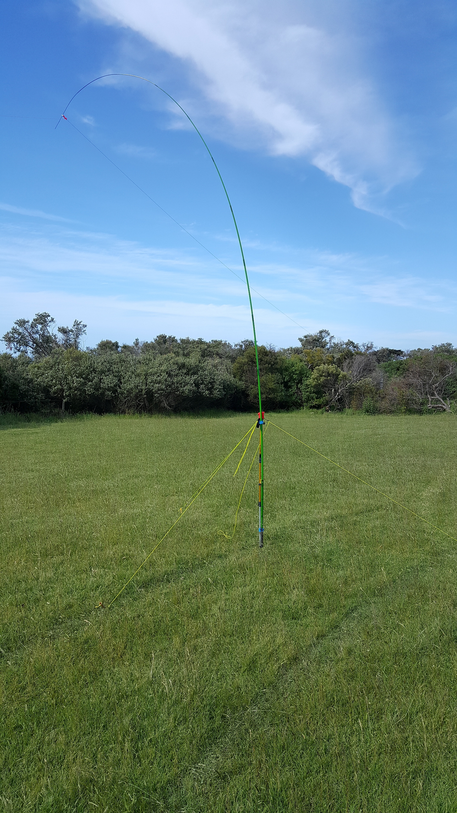
Antenna held from small squid pole – apex around 4m above the ground
To evaluate the antenna a little further, I set it up in a park environment and measured its SWR across 3.5 – 30 MHz using my N2PK VNA. I made measurements using both a small squid pole with the apex around 4m above ground and also with my large squid pole with the apex at around 8m above ground. In each case the end of the antenna were approximately 1m above ground. This closely matched the topology of the earlier NEC models as far as possible.
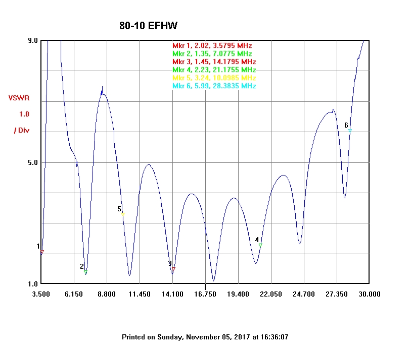
Measured SWR with antenna mounted as an inverted V on small squid pole (apex around 4m above ground)
As you can see, the measured response is a reasonable fit to the model.
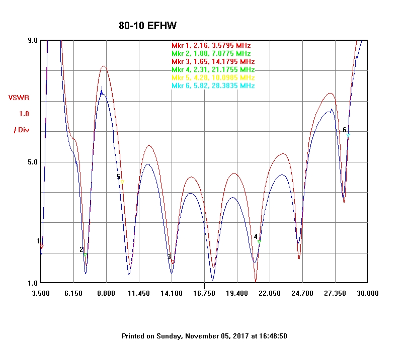
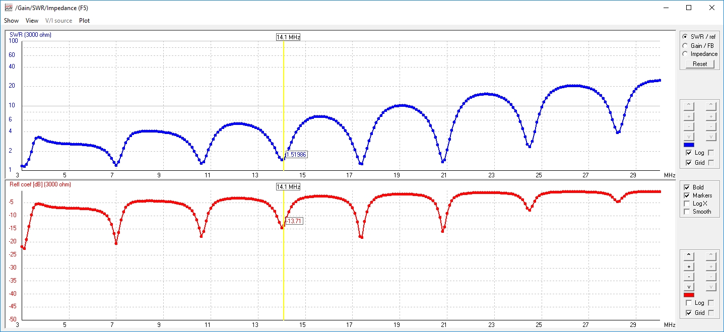
Measured SWR with antenna on small squid pole (blue trace) and large squid pole (red trace with markers)
It is interesting to compare the response using the two different apex heights. As you can see from the chart above, the taller pole (with a necessarily sharper apex angle) results in a slightly higher frequency for each of the SWR dips with slightly better SWR on the higher bands and slightly worse SWR on the lower bands. This reinforces the fact the the setup of portable antennas has a significant effect on the actual SWR encountered.
I have now used this antenna for quite a few activations and found that it works well in conjunction with the built in ATU in a KX3/KX2. It is a long antenna, but this is necessary if you want something that will work reasonably on the 80m band. It also gets a lot of wire in the air which can help with receive sensitivity a bit. By using relatively thin wire, the resulting antenna can be wound on a kite winder and not be too bulky in a pack.
Appendix – NEC2 model
This model uses 22AWG PVC coated hookup wire and is designed as an inverted V with the apex about 4m above the ground and ends about 1m above the ground. To make sense of the SWR analysis, you need to set the characteristic impedance of the system to 3000 ohms as this is roughly what the matching transformer will map to.
CM End fed multi-band using a single coil to adjust resonance
CM
CE
SY L1=2.0 ‘Length from start to coil
SY Lcoil=0.03 ‘Length of coil
SY L2=39.21 ‘Length of whole antenna
SY L=4.45e-6 ‘Coil inductance (4.45e-6)
SY EndHeight=1.0 ‘Height of ends above ground
SY ApexHeight=4.0 ‘Height of apex above ground
SY PoleX=sqr((L2/2)^2-(ApexHeight-EndHeight)^2) ‘X coord of support pole
SY Theta=atn((ApexHeight-EndHeight)/PoleX) ‘Angle antenna makes with EndHeight plane
SY CoilSX=L1*cos(Theta) ‘X position of coil start
SY CoilSZ=L1*sin(Theta)+EndHeight ‘Z position of coil start
SY CoilEX=Lcoil*cos(Theta) + CoilSX ‘X position of coil end
SY CoilEZ=Lcoil*sin(Theta)+ CoilSZ ‘Z position of coil end
GW 1 10 0 0 EndHeight CoilSX 0 CoilSZ 0.00025 ‘Section from start to coil
GW 2 1 CoilSX 0 CoilSZ CoilEX 0 CoilEZ 0.00025 ‘Coil
GW 3 100 CoilEX 0 CoilEZ PoleX 0 ApexHeight 0.00025 ‘Section from coil to apex
GW 10 1 0 0 EndHeight-0.1 0 0 EndHeight 0.00025 ‘Feedpoint
GW 4 100 PoleX 0 ApexHeight 2*PoleX 0 EndHeight 0.00025 ‘Section from apex to end
GW 5 10 0 0 0 0 0 EndHeight-0.1 0.00025 ‘Ground connection
GE 1
LD 7 0 0 0 4.5 0.00039 ’22AWG PVC hookup wire
LD 0 2 1 1 0.1 L 0 ‘Coil
GN 2 0 0 0 4 0.003
EK
EX 0 10 1 0 1.0 0 0
FR 0 0 0 0 3.6 0
EN
Cool, thanks for posting this!
Nice blog and great antenna, been running same system great on northern woods.. As transformer i use two FT240-43 for lower losses with 2 turn primary basic 1:7 ratio and 100pf cap.. Try it, less windings will cause better swr on high end too… 73 de Jari
Thanks Jari. Yes 2 turns will improve the SWR on the higher bands, however you would need the 2 x FT240-43 to provide sufficient primary inductance on the lower bands. In my case, I’m trying to keep the transformer as light as possible as I’m carrying it to the tops of mountains!
Here is another good one for 15W and less.. I run this sometimes on WWFF but mostly 50W with (FT240-43) Owen has nice pages too, loss calculations and so on.. Fair-rite 2643625002 has low loss check this out .. here..https://owenduffy.net/blog/?p=12642
Yes, that’s also an interesting one. Yes, Owen has lots of interesting articles on his site.
Looking for multi band end fed recommendations for about 1000 ft of space and some height available. Trees on each end of my property. What would be your favorite longwire length for 80-10 with 1000 feet of space and how would you feed it ?
Michael, I haven’t experimented much with long wires antennas other than the end-fed’s documented on this blog. My application has been purely portable deployments, so can’t comment much on home long-wire installations. Certainly there are many to choose from including Windoms, double Zepps, G5RVs, random wires and many variations of the the end-fed’s I’ve described. Depends somewhat on where exactly you want to feed it. If you google these antennas, you’ll come across lots of information.
Sorry
“What antenna do you use with better results?
Santi
EA3KX
Hi Santi,
I’m not sure I understand your question. I’ve found this antenna works well for SOTA activations.
73
David
VK3IL
Good morning David
Sorry for delay and sorry for my question.
The real question is :
What do you thing better antenna for sota activation :
– The trapped five band EFHW sota antenna
or
– The multiband end-fed 80-10 m antenna
What do you prefer ?
Thanks in advanced
Santi
EA3KX
Hi Santi, OK, now I understand. For SOTA, it depends whether the transceiver has a built-in tuner. If it doesn’t then the 5 band EFHW is better as it can be built to need no tuner on the 5 bands. If you have a tuner, then the 80-10 EFHW is easier as it is lighter, smaller and less fragile given it has no traps. However, it needs a tuner to get the SWR low enough on some bands. Of late I’ve been using this antenna mainly with my KX2.
73,
David.
Dear David,
Many thanks for your answer.
I’m using a KX3 with ATU.
I wilt try to make a Multiband 80-10 m antenna.
See you
Santi EA3KX
You say “The wire was cut to 40m length and then trimmed when set up as an inverted V to minimise the SWR at 7.090 MHz” why do you optimise for 40m band when it is 1/2 wave for 80m?
Really nice write up – thanks very much. I use mine with a kite, and people do not believe I run only 4 or 5 watts.
David – M0TFY
Hi David,
As you can see from the SWR plots, it’s not really possible to get the dips all aligning well with the amateur bands. Hence you need to choose which frequency you want to optimise for. In my case, I chose 7.090 as that’s probably the most popular frequency here in VK for SOTA. It is quite arbitrary, so one could choose 80m too if that was where you wanted to optimize.
73, David VK3IL
A really cool experience is using a kite antenna where you can reel in and out whatever wire length you like to get a great SWR. These matching transformers are still necessary to keep the static buildup on the wire from destroying the input stages of the receiver. WATCH IT !
Yes, I agree! See my article on the kite antenna: Experiments with 160m antennas
73, David VK3IL
Dear David,
Inductance of the coil is far too high.
With 0,9…1,4 uH both 15 m and 10 m bands would just on spot.
Kind regards “Val” OE5VJO (ex ZS2VJ)
Hi Val,
Thanks for your feedback. Not sure how you came to that value for the inductor? I tried modelling with 1.1uH and this results in about 8:1 SWR (for a 3000 ohms impedance) at 28.4 MHz which is significantly worse than with the 4.45uH inductance I used. Are you perhaps using a different antenna configuration (something other than an inverted V with a 4m apex height)?
73
David
VK3IL
Hi David, thank you for the response.
When seven years ago I moved to Austria I found out that the only antenna I could erect is a EF LW! My house is surrounded with very high tries and a roof made of aluminium “tiles”. That is why I tested three “commercial” and some other HAM’s design
of EF LW.
I settle down with 50 to 1,800 Ohm ratio or 1/6 turns. My antenna is about 8,0 m over ground. I start with 20,3 m length and than with something about 40,0 m length. I do not know the length exactly as I trimmed it for 7,110 MHz. With 20,0 length it is not too much problems with 15 m and 10 m resonance. But at 40 m length the DL7AA advice works.
My design was repeated in ZS “commercially”. In Austria about 50 antennas were made.
Give me your E-mail address I will send you more information.
Yours Val
hi i have ALINCO all model hf transceiver ITS DX-SR8 , CAN I USE A HF END FED ANTENNA EFHW80-10- 10W SINGLE WIRE ON MYALINCO HAM RADO.
Hi Kenneth,
You can certainly use the EFHW80-10 antenna with this radio, however it is a 100W radio and the matching unit is not designed for 100W, so you would need to replace it with a larger unit (e.g with a FT240-43 core). You will also very likely need to add a common mode choke to the feedline (about half way between antenna feedpoint and the radio) to prevent RF in the shack.
73
David
VK3IL
Hello I would like to make a similar antenna on 40 : 10 m. I don’t know how many uH they would have. Thank you in advance.
Hi Liviu,
Whilst you could create an antenna from 40m up, it would not cover as many bands. It would only be possible to cover 7, 14, 21, 28MHz bands as that’s where the frequency multiples land. You would need to model it I think to see where the actual SWR minimums would land, which would then also inform the amount of inductance needed to shift the upper band minima to the best locations. Unfortunately I don’t have time at present to do the modelling, but you could take the model in the article and modify it if you are familiar with 4nec2 or similar software.
73 David VK3IL
Hi David,
Thanks for the simulation. I ran it with 4NEC2 and it shows a segmentation error because the coil length is so short at 3MHz.
Interestingly if you increase the coil length to 9cm then you get slightly better SWR to your 3K load across the bands.
I am not sure what NEC is doing here as I presume it keeps the RLC values the same. Maybe it is altering the coupling between the two wire sections of the antenna.
73’s,
Michael.
EFHW antenna can have good SWR on many bands. However, current distribution (and pattern) is good on one band only. Using antenna with horizontal polarization at very low height is not good, even for NVIS. Optimal height for NVIS is 0.18 wavelengths, say 16m for 80M band. You need to model common mode currents on coax shield. It is easy, just add extra wire the same length as feedline. To decouple coax from antenna you will need about 10 x feed impedance choke – say 10 x 2.4 kohm = 24 kohm. This is only possible for single band choke. Nobody wants to get irradiated and get sick. I hope you have been using only very low power with this antenna.
Hi Tino,
Thanks for your interest in the project. Yes, I’m fully aware of the limitations of this antenna. When operating portable with very light weight equipment, you have to accept some compromises. I agree that I could have modelled common mode currents on the shield of the coax, however in this deployment model (portable field operations) the coax is typically only 1-2m in length and mostly sitting on the ground, so modelling it is not simple. As you can see from the measurements, it is practically quite close to the model anyway.
In relation to coax decoupling, again, the deployment is field portable and so the TX power is typically 5-50W only. Decoupling the feed line close to the transformer will likely cause issues as EFHW antennas need some form of counterpoise to work and the feed line plays this role in the absence of any separate wire. Even at 50W, I have not had any issues with “RF in the shack”. The RF exposure calculation for 7 MHz at 50W provides a compliance safety distance of approximately 60cm, so even with an inverted V field deployment, it is easy to remain at a safe distance.
Kudos man. We use the same antenna design for our Field Day with great success. Your model is great as well. Cheers.
John, kx4o