
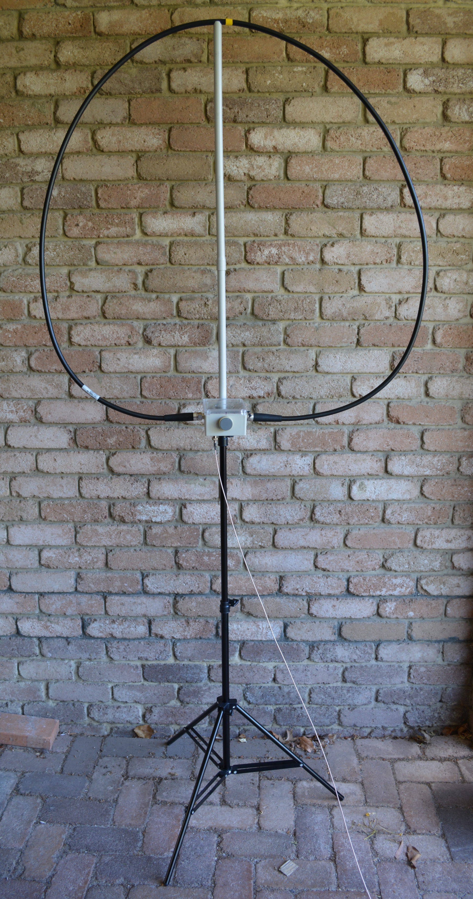
My magnetic loop inspired by DG2IAQ’s design
I have long been intrigued by the magnetic loop antenna and have been reading widely on the Internet on the subject for some time. I also saw Tony VK3CAT’s AlexLoop and thought it would be fun to try and make my own as an interesting alternative antenna for SOTA. The independence from large squid poles and small antenna footprint that would be possible appealed too.
I wasn’t totally convinced on the small loop matching approach used in the AlexLoop for SOTA applications, so explored further and came across the design by DG2IAQ using capacitive matching.
Whilst this has it’s limitations, principally more ground loss due to the proximity of the capacitor and it’s E field to the ground and higher common mode current due to the high impedance feed point, the convenience of the set up made for a good trade off.
The key to a successful magnetic loop appears to be keeping the loop resistance as low as possible. In fixed loops, that means soldered joints everywhere and either a butterfly or split-stator capacitor to avoid lossy sliding contacts (or a vacuum variable capacitor).
I wanted to keep the antenna as light and compact as possible, so I selected a split stator receiving capacitor with a 6:1 reduction drive to make the tuning usable. These aren’t so easy to find these days. I obtained mine from MidnightScience. The capacitance range was nominally 23 – 182pF with the two sections in series but it actually went down to around 4pF which allowed a very wide tuning range.
The plate spacing on this capacitor is 0.01″. This in theory provides a voltage breakdown rating of around 1500v when the two sections of the capacitor are placed in series. This provides a potential power rating of up to 50w on 40m.
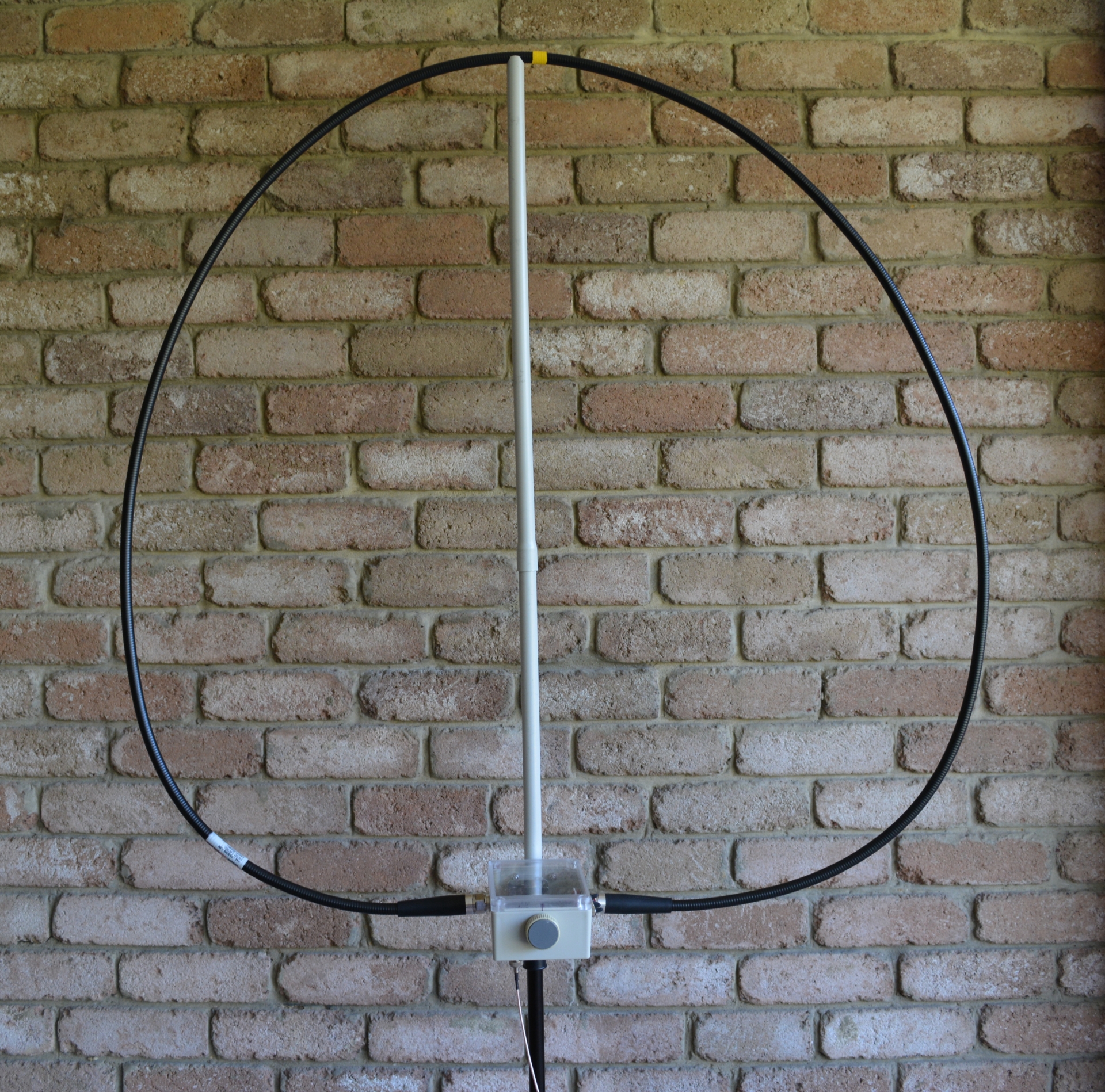
The heliax loop is supported by a two section pole made of 20mm conduit. It is stiff enough to not require a horizontal support.
For the loop I used a 3m length of LDF4-50B 1/2″ Heliax that I bought at a hamfest a few years ago. This type is “super flexible” and can be coiled into quite a small package, but still has a solid copper outer. It was also fitted with high quality N connectors on each end. This is probably about as good as you can get while remaining backpackable.
A 3m loop length resonates with the chosen capacitor from just below 7MHz to about 28.300MHz which makes it usable on the bands from 40m to 10m.
To keep the loop resistance as low as possible, I used silver plated N jacks on the capacitor housing and connected these to the capacitor with copper strip soldered at both ends.
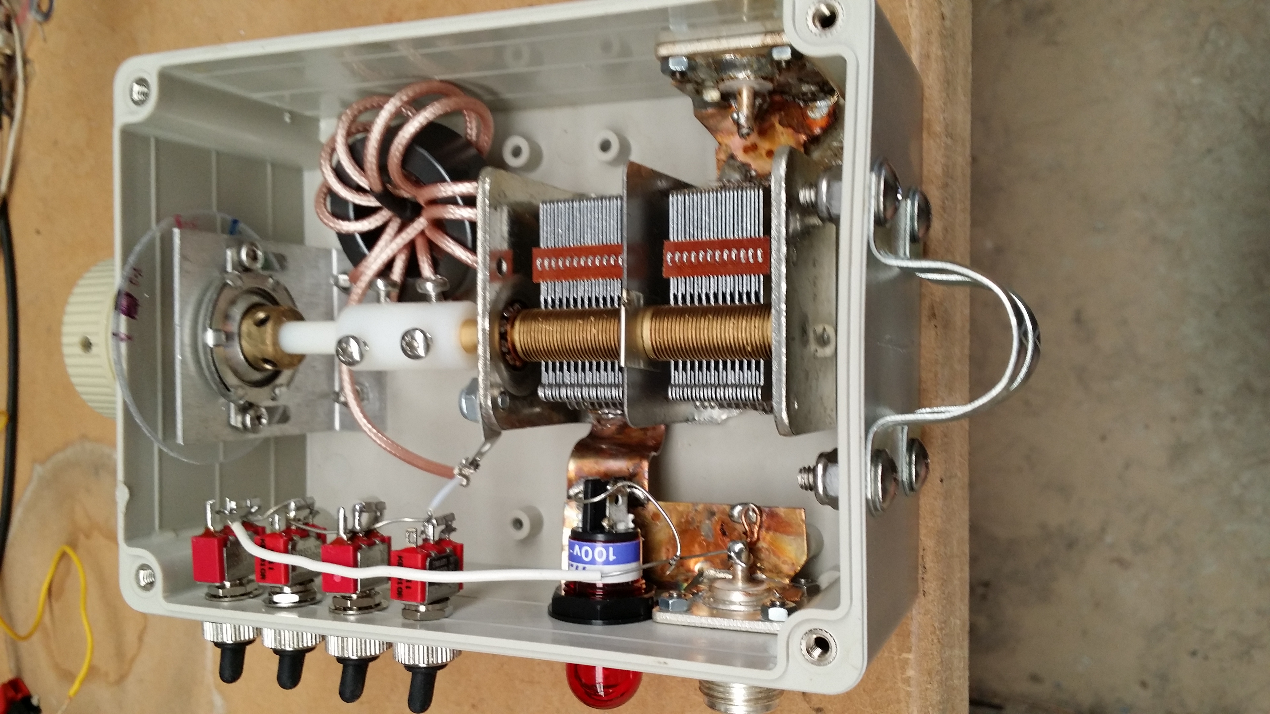
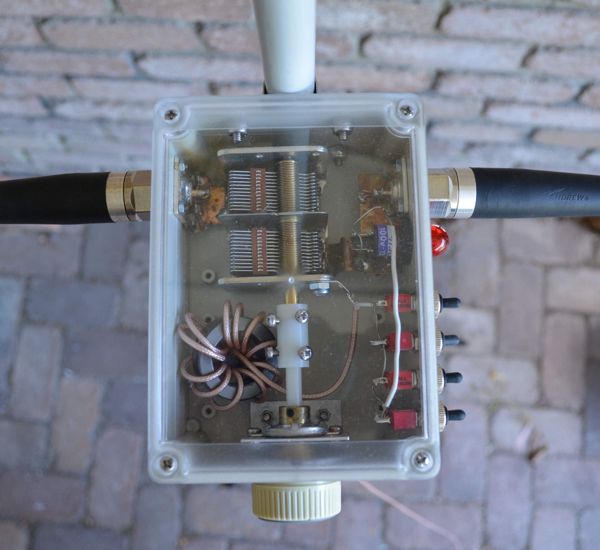
The internal layout of the tuning and matching box.
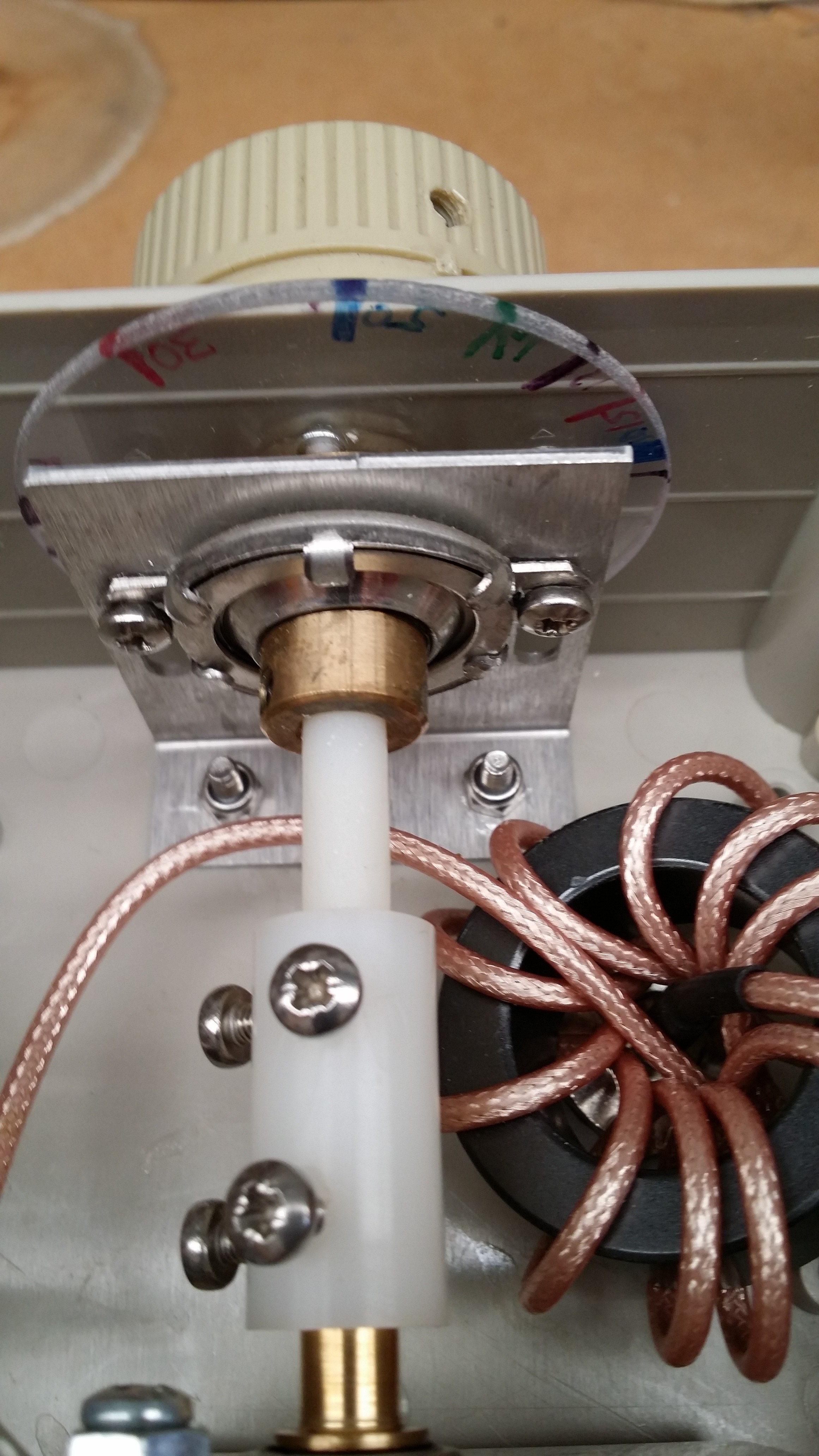
A close up of the 6:1 reduction drive, tuning card and the common mode choke.
The 6:1 reduction drive for the tuning capacitor makes it possible to manage the extremely narrow bandwidth of the loop reasonably. I added a tuning dial marked with the band positions to help get the rough tuning right. This is attached to the reduction drive on the slow side.
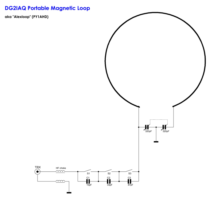
This the circuit diagram of the loop courtesy DG2IAQ. In my loop, there are 4 matching capacitors and switches and the main tuning capacitor is 364pF
Magnetic loops can be fed in a number of ways – coupling loops, gamma feed, toroidal coupling and capacitive coupling. I decided to give capacitive coupling a go following the ideas of DG2IAQ. This is also known as “Army Loop” or Paterson coupling. You simply feed the loop directly across half the capacitor with a series capacitor to match the predominantly inductive load. The series capacitance required varies by band, but is insensitive enough that a single value provides a good match across a given band.
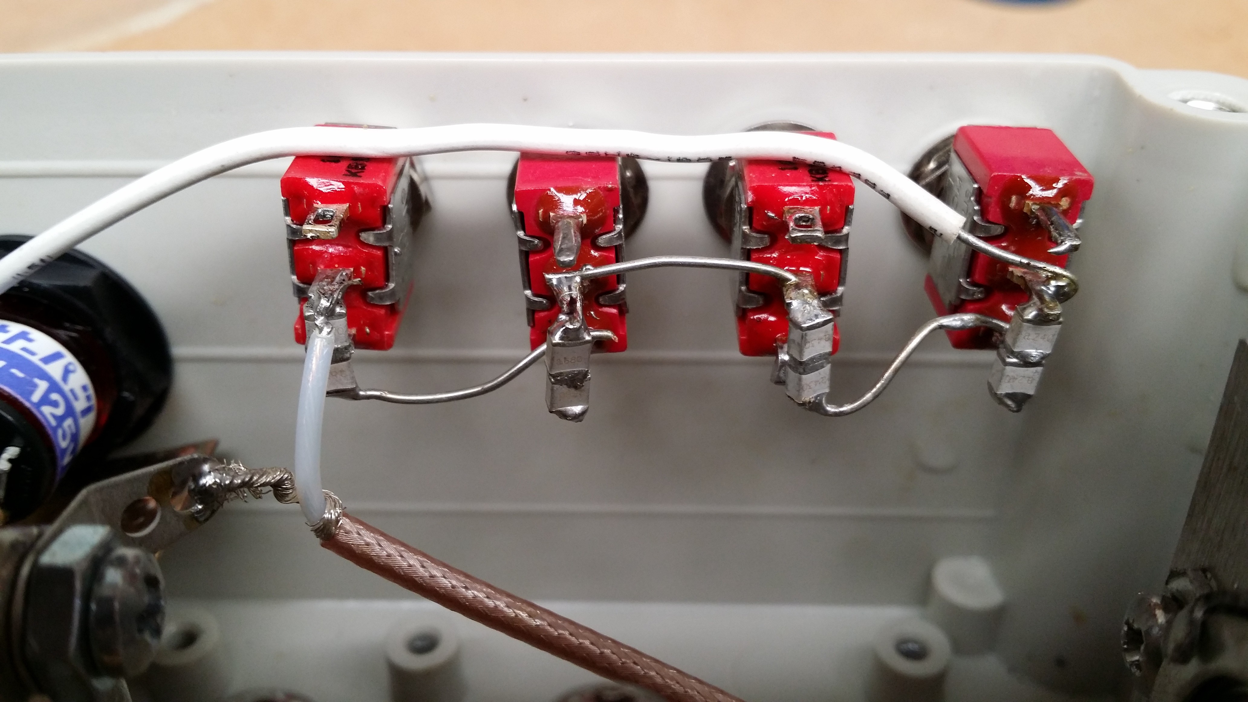
Following DG2IAQ’s approach, I added 4 silver mica capacitors in series with a switch across each to bypass it. In this way I could select a wide range of capacitance values with different switch combinations. I could probably have managed with 3 switches, but 4 gives more flexibility.
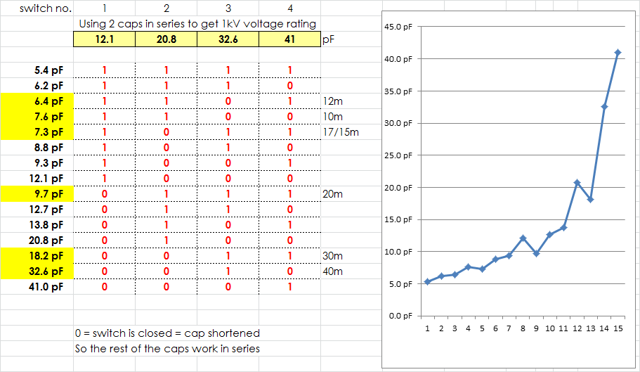
This is the range of matching capacitances that are possible in my loop. The spreadsheet is again courtesy DG2IAQ. The capacitance values that best match each band are also shown in the table.
The required capacitance to match the loop ranged from 33pF on 40m to 6pF at 10/12m. This resulted in my using measured capacitance values of 12.1, 20.8, 32.6 and 41pF with each value made from two capacitors in series (described later).
Initially I used 500V Silver Mica capacitors, but these proved problematic (see below).
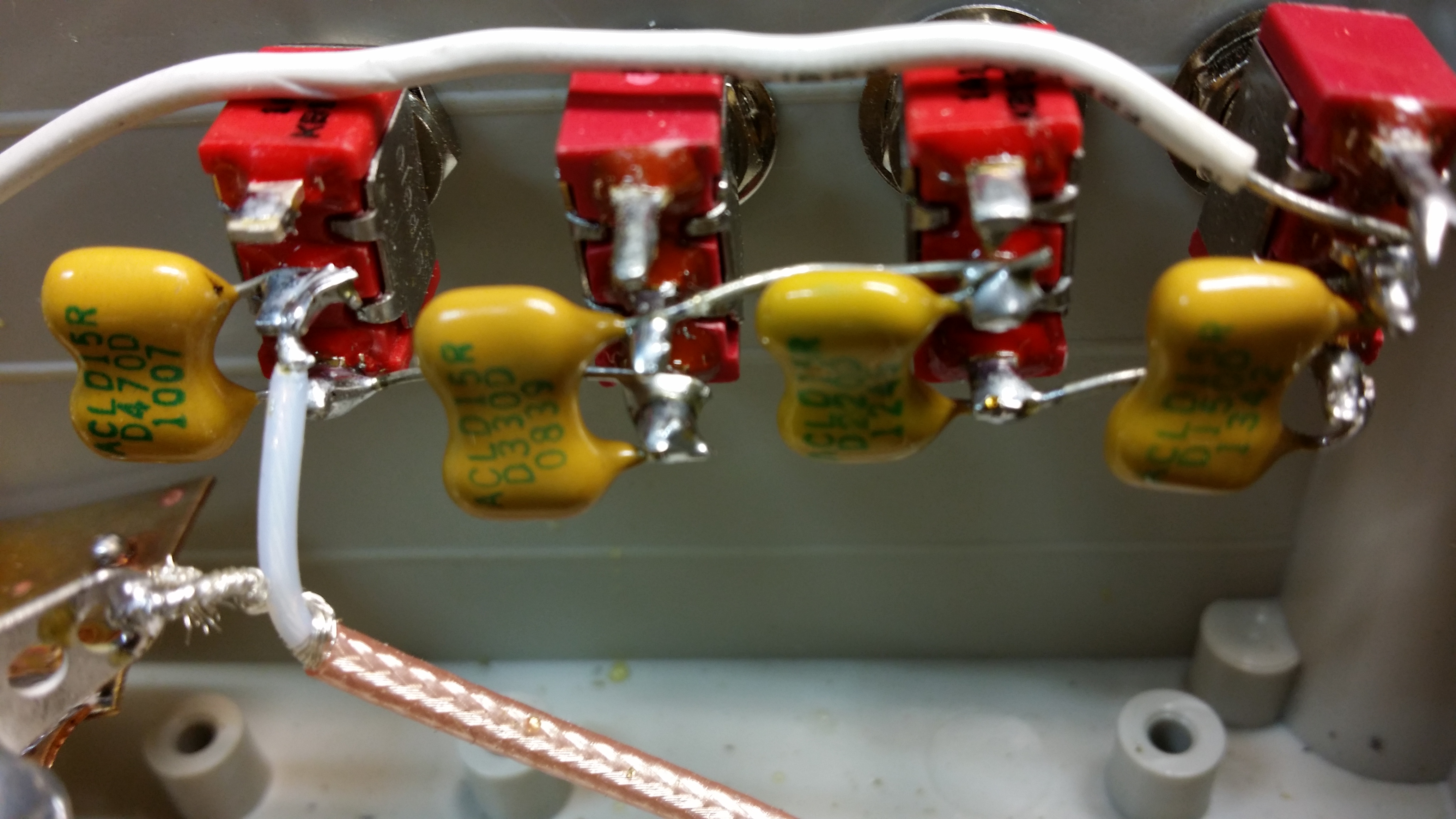
Silver Mica capacitors for matching proved not to be a good choice.
The only other component needed is a feed line choke to keep RF off the feed line. This was fabricated with a FT140-43 toroid with 13 turns of RG-316 coax. This proved to be only just adequate given the high impedance feedpoint (see later measurements of common mode current).
The tuning unit is mounted in a waterproof polycarbonate box.
I built the variable capacitor, matching capacitors, switches and feed line choke into a waterproof polycarbonate box with a BNC socket on the bottom to attach a feed line. This provides a neat installation with only the loop cable and the feed line as separate components.
I also built in a neon indicator to act as a rough tuning indicator. I found that this really only lit up above 10W of power, so in practise is of limited use. This simply has both connection tied to one side of the tuning capacitor and the RF field strength inside the bulb causes the neon gas to glow.
When it came to testing, I found that the matching capacitors worked quite well with an acceptably low SWR across the 40m through 10m bands (it only covers up to about 28.300MHz on 10m). This coverage range is greater than I had expected and makes this a very versatile antenna.
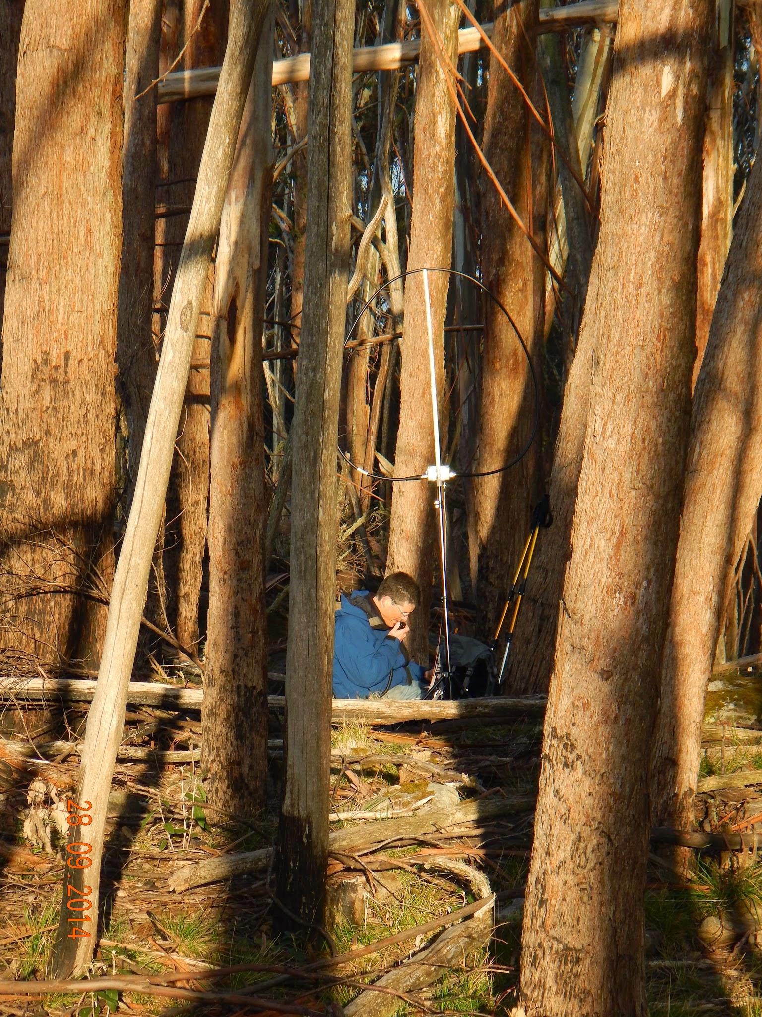
Operating with my magnetic loop antenna at Pyramid Hill (photo credit: Allen VK3HRA)
I tried it out in this configuration for a SOTA activation and was pleasantly surprised by its performance. I had good signal reports of similar level to those I had received earlier in the day from my trapped EFHW. I was driving the antenna with my 20W KN-Q7A SSB transceiver.
Matching capacitors
An interesting aspect of testing was the performance of the silver mica capacitors. I had thought that at 500V rating, they would be OK for this application and reasonably low loss. I found that at 30W continuous carrier, they heat up quite significantly and with this heating the capacitance value changes enough to de-tune the loop so that the SWR goes from about 1.2:1 to 6:1 within 15-20s! Clearly that’s not going to be good for any medium-high duty cycle mode.
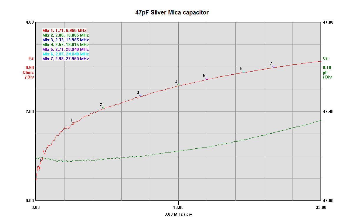
This is a plot of the capacitance and equivalent series resistance of a 47pF Silver Mica capacitor. It was taken with my N2PK VNA with an RF-IV measurements head (which is necessary to measure such small resistances with any degree of accuracy – should be within 5%)
Characterising the 47pF Silver Mica capacitor shows a equivalent series resistance at 7MHz around 1.5 ohms. At 30W, the current through the capacitor is approx 775mA resulting in a power dissipation of 900mW this is clearly enough to heat the capacitor significantly.
The second problem is the voltage across the capacitor. I had assumed that 500V rating of the capacitors would be more than adequate, but had not done the maths. Turns out that at 20W level, the peak voltage on the matching capacitor for the worst case band is 1080V on 17m! You really need 1kV rated capacitors even at only 20W power level for this type of matching.
Pairs of series connected ATC800B porcelain SMD capacitors work much better
The challenge was to find a low ESR, high voltage capacitor with a near zero temperature coefficient! Fortunately such capacitors exist. Advanced Technical Ceramics make some very nice porcelain SMD capacitors that fit this specification (ATC700B series high voltage variant). However obtaining them in small quantities is impossible at present. Thankfully a closely related type – the ATC800B series – is available from RF-Microwave in Italy in small quantities. This series are very low ESR, NPO, 500V SMD capacitors. By using two in series, you can obtain the required 1kV rating in a compact enough form for this application.
Performance measurements
I measured the resultant performance of the antenna using my N2PK VNA and the plots across the bands are at the end of this article. The following table summarises the performance:
| Band | Frequency range | Q | SWR bandwidth [kHz] |
| 40m | 7.000 – 7.300 | 312 | 22 |
| 30m | 10.100 – 10.150 | 272 | 37 |
| 20m | 14.000 – 14.350 | 315 | 45 |
| 17m | 18.068 – 18.168 | 299 | 61 |
| 15m | 21.000 – 21.450 | 223 | 94 |
| 12m | 24.890 – 24.990 | 173 | 144 |
| 10m | 28.000 – 28.480 | 97 | 289 |
As expected, the Q decreases with increasing frequency. Not sure I can explain why it dips on 30m though!
| Band | Maximum power (no arc) |
| 40m | 50W (no significant heating for 1 min CW tx) |
| 30m | 15W (occasional arcing) |
| 20m | 22W |
| 17m | 10W |
| 15m | 10W |
| 12m | 12W |
| 10m | 30W (limited by interference to transmitter) |
Again 30m performance appears anomalous.
The 30W limit on 10m was set by the interference I was getting to the transceiver when transmitting above this power level – the transmitter (an IC-7000) would switch off it’s power! I think this may be due to RF getting in to the transceiver control circuits via either direct radiation or common mode currents on the transmission line. The power supply was a battery for these tests and the whole transceiver and battery were isolated from ground.
To investigate common mode currents, I used a simple current transformer connected to a 50 ohm termination and RF voltmeter. I found the following currents on the outside of the transmission line using 20W transmit power (about 630mA RMS).
| Band | RF current on cable [mA rms] |
| 40m | 8 |
| 20m | 37.6 |
| 10m | 43.2 |
The currents are not excessive and are more than 20dB down on the actual transmitted current. The increasing common mode current with frequency is consistent with the lowering impedance of the common mode choke. The choke is optimised for lower frequencies (where I’ll mostly be using this antenna). A second choke with fewer turns in series with the first would likely reduce the common mode current on the higher frequencies, but is probably overkill for the application.
Conclusion
This antenna so far has met my expectations and is weight comparable to other SOTA antennas I have. Total weight: 2.44kg (my multi-band EFHW antenna weighs 1.91kg including the squid pole).
Tuning is fairly easy on the lower bands, but is quite challenging on 10m-15m due to the significant effects of hand capacitance at those frequencies. Even though the knob is separated with a nylon shaft from the tuning capacitor, the frequency shifts several tens of kHz when you move your hand away. Hence tuning is a bit tricky.
Now it’s time to take it into the field and try it out in comparison to a dipole and my EFHW!
Here are a couple of final photos of parts of the antenna for interest:
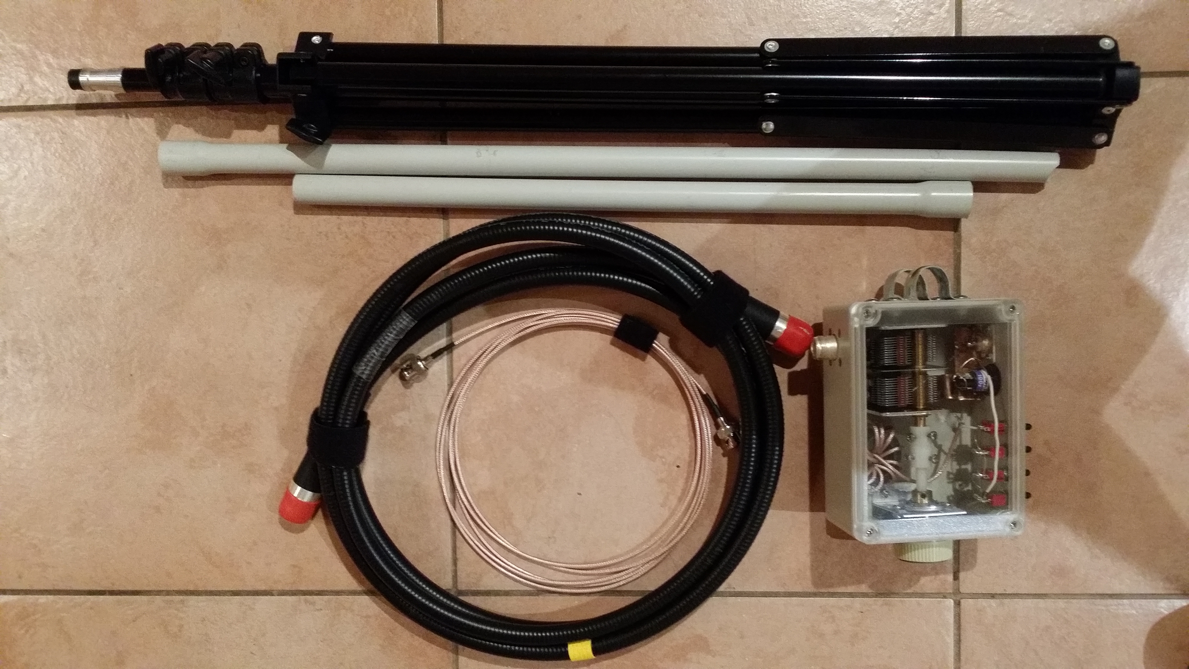
It breaks down to quite a small size and fits easily in a pack.
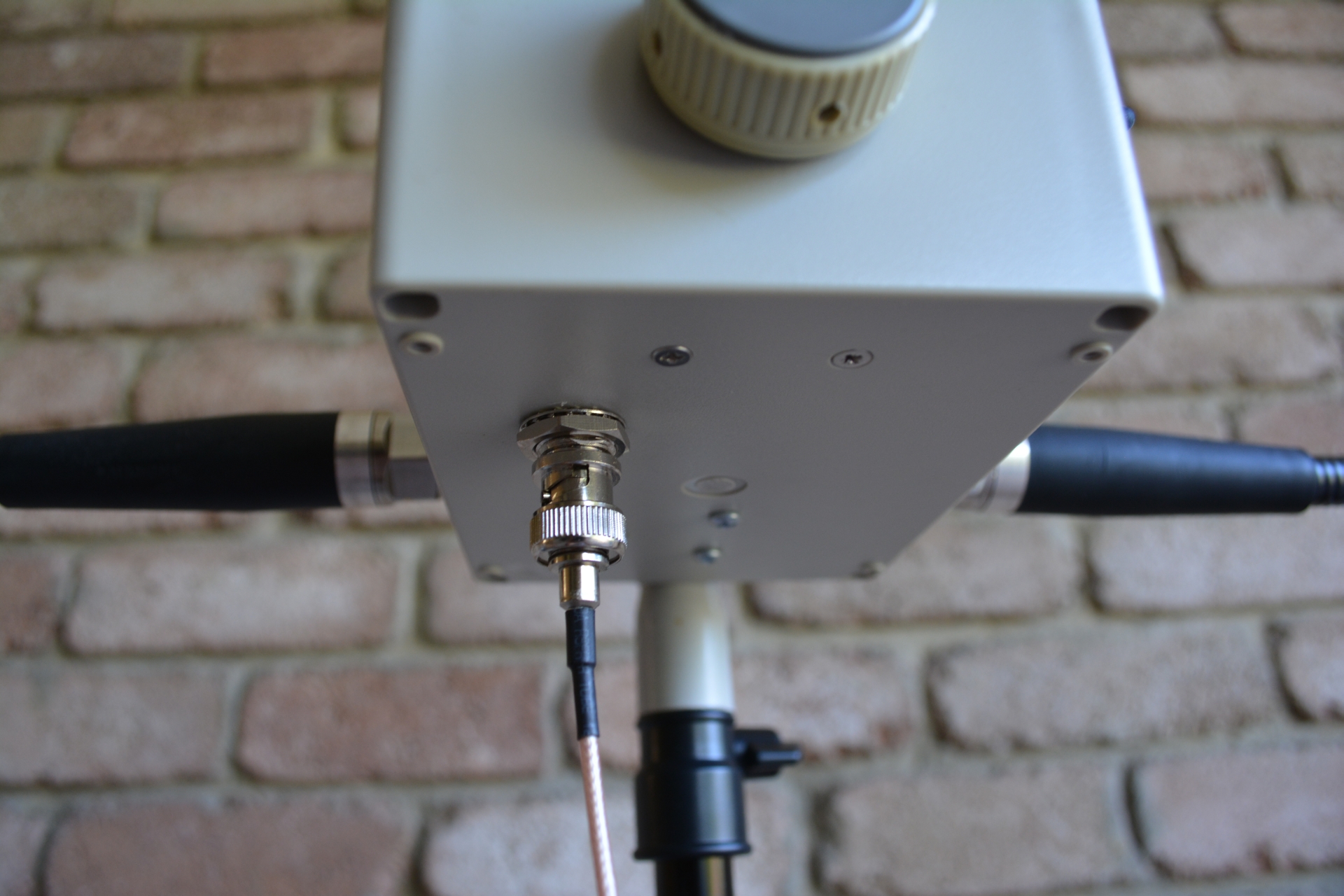
The feed line attaches to a BNC socket on the bottom of the box
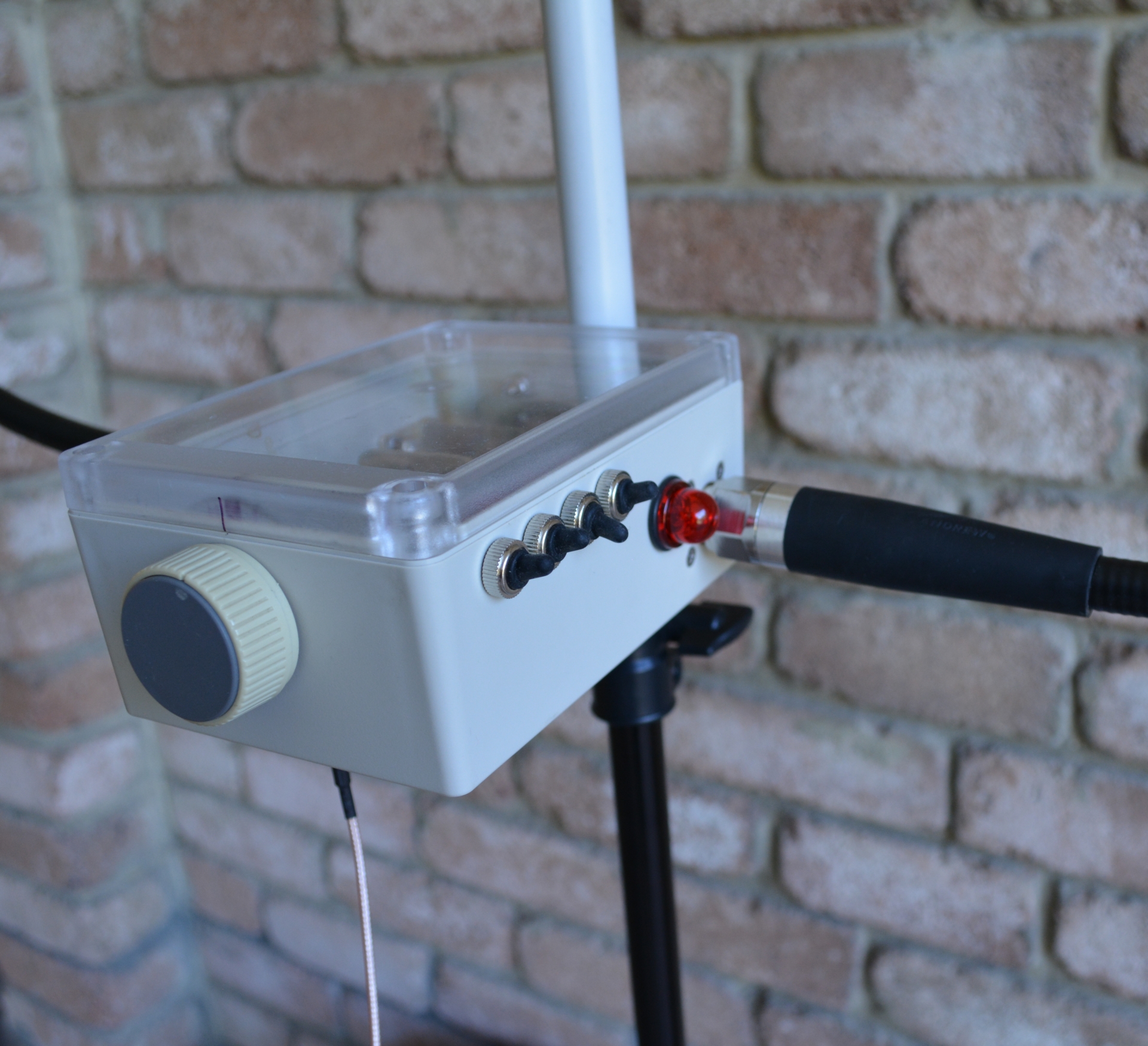
The switched select the appropriate matching capacitance and the red neon provides an indication of power output above 10-15W
SWR plots
Here are the SWR plots for each band for reference – click on them to get a bigger image.
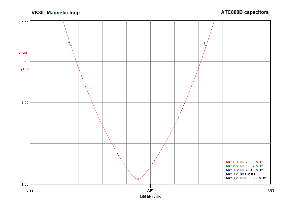
40m band – low end

40m band – high end
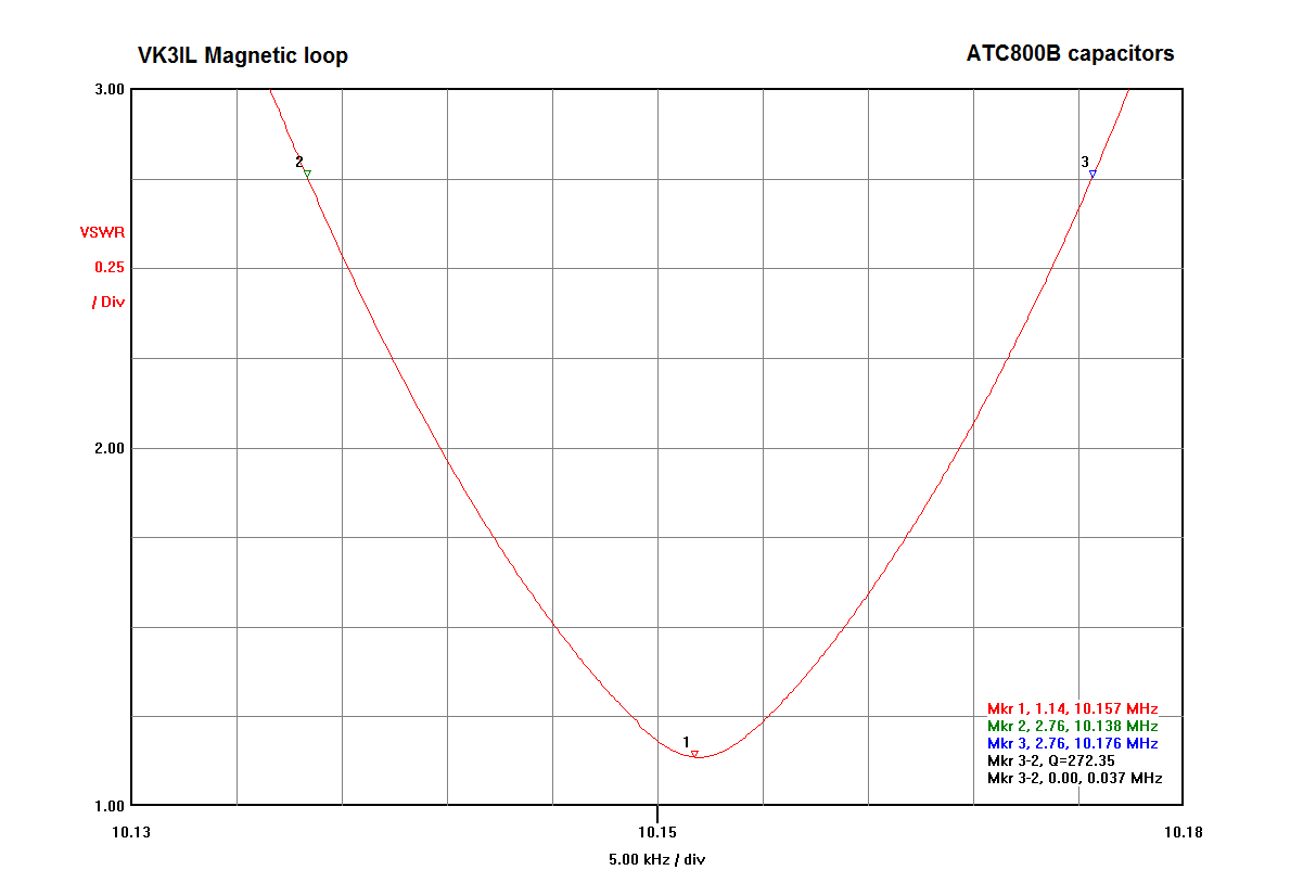
30m band
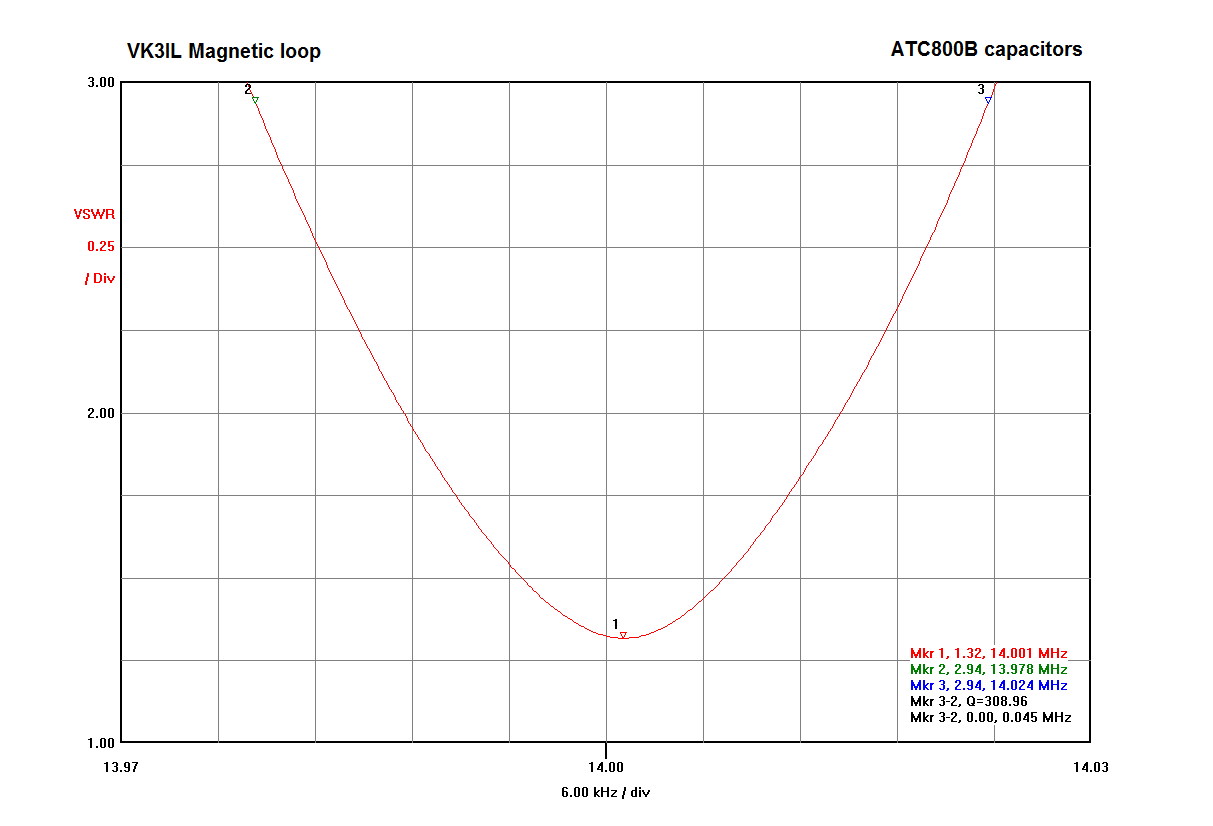
20m band – low end
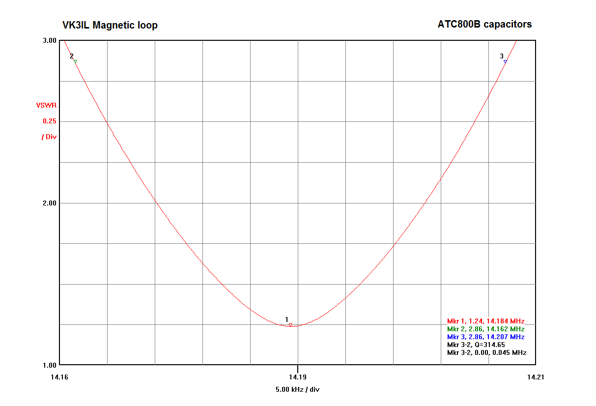
20m band – mid band
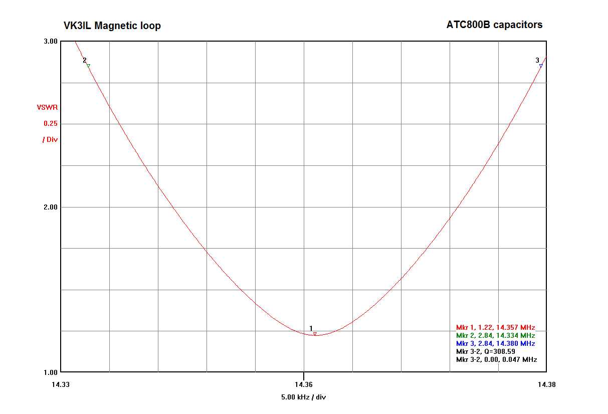
20m band – high end
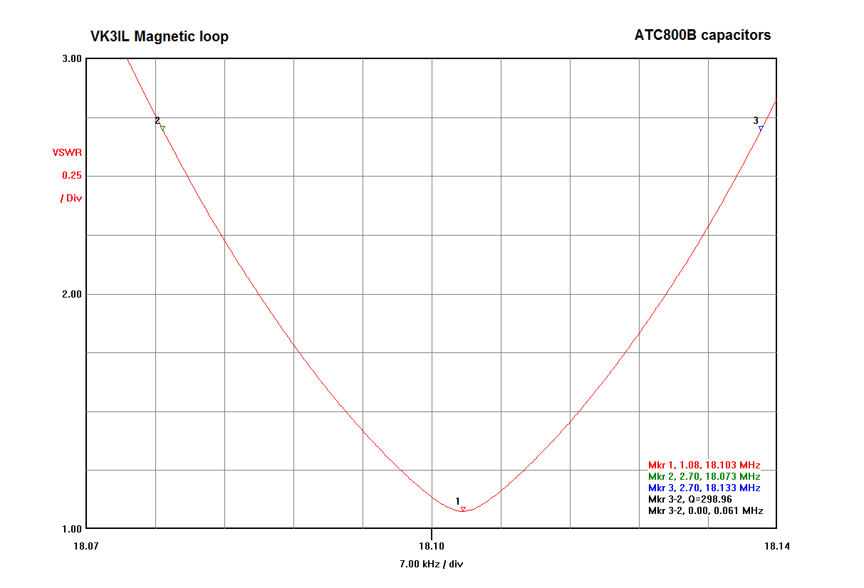
17m band
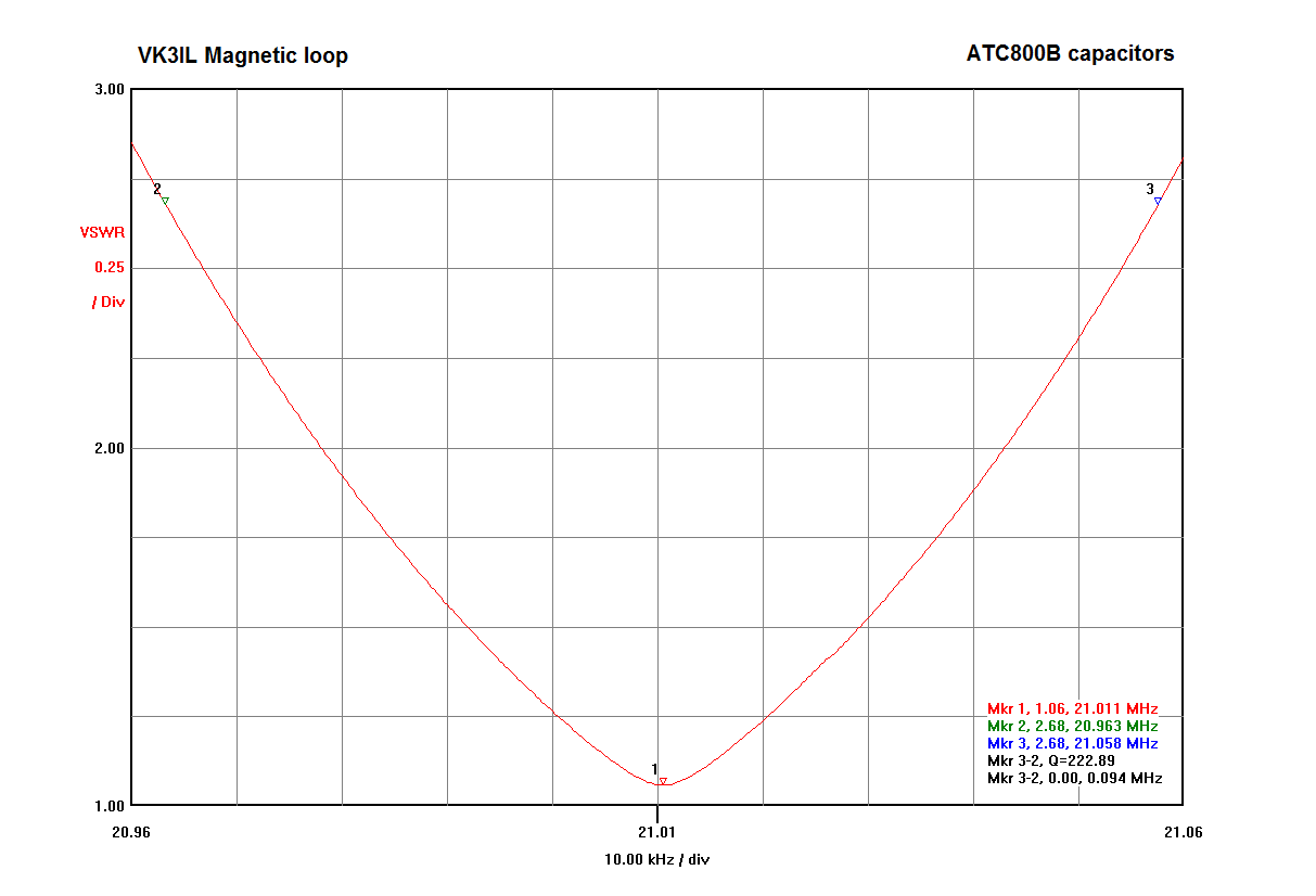
15m band – low end

15m band – high end
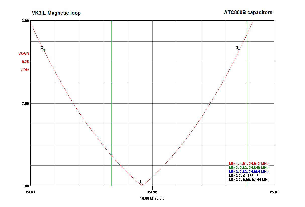
12m band (green lines are band edges)
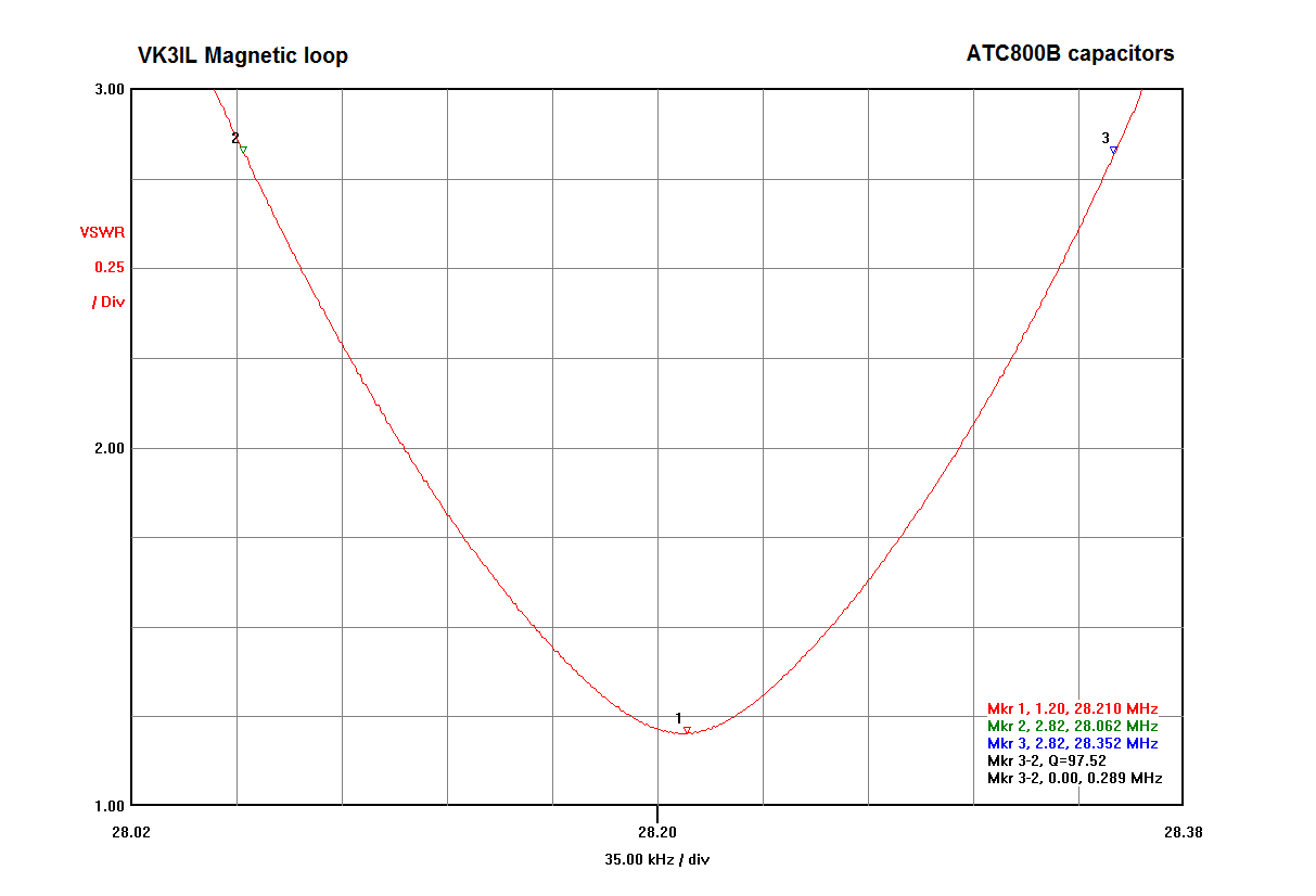
10m band
Pingback: Bill Head and Pyramid Hill - 29 September 2014 - VK3IL BlogVK3IL Blog
Great information David, I have been wanting to build one of these. Thanks for the capacitor info.
Cheers:
Rob
Vk2qr
Thanks Rob. Good luck with it – maybe we can do a loop – loop S2S one day!
Nice loop and solid reasoning/measurements to back up your choices.
According to Owen Duffy’s efficiency calculator using VSWR bandwidth, the efficiency of your loop is about 1.3% on 40m and 26.9% on 10m: https://owenduffy.net/calc/SmallTransmittingLoopBw2Gain.htm .
Why were you doubtful of using the auxiliary loop method for feeding the larger loop? That method has the advantage of not requiring a common-mode choke, as the feed method itself is inherently resistant to common-mode currents (as you seem to be aware). Were you concerned about the ease-of-use (set-up/tear-down)?
One other portable option you might consider is using a thin copper strap. That can be soldered permanently to your variable capacitor yet still be carefully rolled up for transport. The problem with a thin strap is supporting it, as it is so flimsy that it will require a bulkier support structure (like one or more cross bars). To estimate the RF loss of the flat strip you can use W9CF’s calculator to estimate the equivalent round-cross-section conductor exhibiting the same loss as the strap: https://fermi.la.asu.edu/w9cf/equiv/ (URL seems to be down now, unfortunately).
Thanks for the comments. I ended up choosing capacitive coupling as it allowed a physically simple arrangement for a portable loop that would be compact and quick and easy to set up. Even with the choke in my antenna, there are certainly common mode currents present, but I haven’t noticed any problems due to them. This would probably not be the case if I was trying to run higher power, but at QRP it seems to work fine. At some stage I plan to take this loop out in the field with a WSPR set up and do some comparative signal strength measurements between a dipole and the loop. Will be interesting to compare to the theoretical loop efficiency.
Nice clear description. Thanks for going in details about the capacitive matching, I’ve seen this being used, but noticed that many seem to avoid this technique, although MFJ have now employed it is their loop tuner (MFJ935)
73s
Richard SO5GB
Thanks Richard. I suspect people avoid capacitive matching as it requires a variable (or switched capacitor) rather than the relatively simpler loop matching. I went with this model as it made portable setup slightly easier.
I would be very interested to see the tuning capacitance overlaid on the matching cap graph
https://i2.wp.com/vk3il.net/wp-content/uploads/2014/10/Image2-2.png
should you need something to fill those long unused hours.
The tuning capacitance required will depend greatly on the actual loop size used. In general you will obviously need more capacitance at lower frequencies and thus the points would follow a similar shape to the matching capacitors. Not sure what insights that would provide though?
Hi
Great project look forward to trying one of these but what’s with the led and how does. It work please
Hi Dylan,
The “LED” is actually a neon bulb. It has both its leads tied together and then to one side of the capacitor. I works on the principle that the high RF voltage will form a corona discharge inside the neon and thus cause the gas to be ionized and glow. As I note in the article, this only works above 10W and so is not really worth including. I’d leave it out.
73 David VK3IL
Super Arbeit
Danke Erich
Thanks. I chose this method of coupling because it eliminates so many things that can decrease efficiency like coupling loop spacing, coupling loop length, shape of coupling loop, top or bottom coupling loop placement and shape of coupling loop. And like you said SO much easier to set up. I use different loop sized for the band i want to operate on.
Cool. Really good handy loop antenna.
Do you remember where can I find insulator (white part) between capacitor and reduction drive?
Cheers, 73
Hi Erhan,
Thanks for your interest in the project. If I recall correctly, that spacer was from the supplier of the variable capcitor and reduction drive – Midnight Science. Unfortunately they no longer seem to be in business. I would look for 1/4″ shaft extenders if you have the capacitor. Here’s one site I found in a quick search: https://www.electronicsurplus.com/1-4-nylon-shaft-extenders-approx-3
73 David VK3IL
Thank you David,
The web page you wrote is inaccesible for now but I will try later on. I have plenty of capacitors, mostly butterfly type.
73 Erhan
TA2WK
I know this is quite an old article but it is very interesting – thank you for taking the time to write it.
How did you go about calculating the fixed capacitor values?
Hi Olly,
Sorry for the slow reply. The fixed capacitor values were chosen to enable the right amount of capacitance to be selected for each band. The capacitance required for this loop is between about 6 pF and 33 pF from 40m to 10m. The combination of capacitors allows a reasonably linear range of capacitance to be selected using the switches between those values. It’s of course also limited to the available standard values. The combinations are illustrated in the image in the article based on the actual measured values of the capacitors. I don’t have the unit easily accessible at present, but I recall the capacitors were constructed from series combinations of the ATC800 capacitors as follows: 2x24pF, 2x43pF, 2x68pF and 2x82pF. When wired in series, these came out to the values in the article. Naturally there will be some small variations, but they will be close enough.
73 David VK3IL
Thank you for the comprehensive response!
73