With the erection of my new horizontal loop antenna, I’ve found all of a sudden that I have quite a bit more signal for my transceivers to listen to. However, that’s brought with it the problem that it’s also picking up very strong broadcast band signals that are overloading at least some of my rigs front ends. In particular, my KN-Q7A has little protection from this sort of overload and is badly affected to the point of being unusable with this antenna. This is a known problem with the rig and is simply a limitation of it’s basic design.
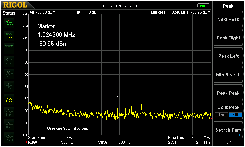
To see how bad the interference was, I connected the antenna to a Spectrum Analyzer. The result is shown below.
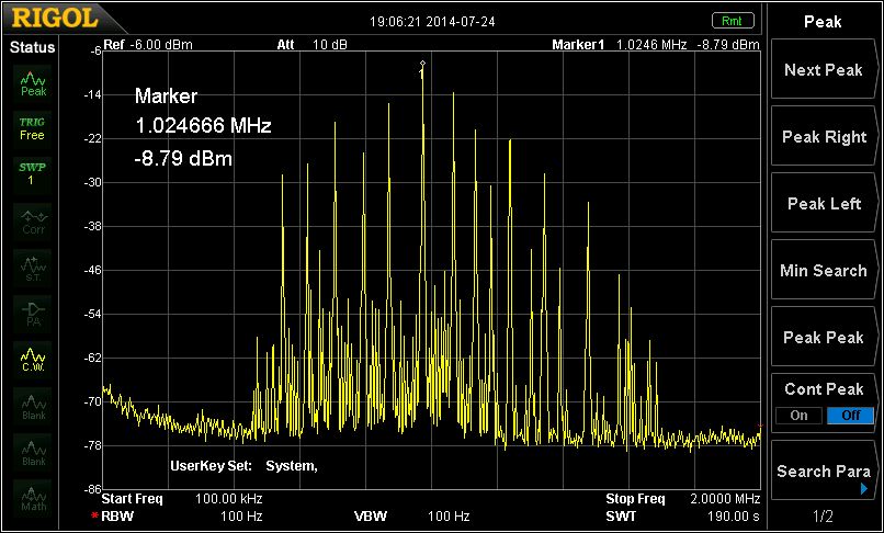
As you can see, the strongest signal is ABC 1026 at only -9 dBm – that’s greater than S9+64dB! The sheer number of similarly strong signals is a bit much for many simple receivers to cope with.
The answer was fairly obvious – a broadcast band filter. I looked at the commercially available units and found that filters capable of being transmitted through at the 100W level were expensive, so I decided to build my own as they are not complex devices.
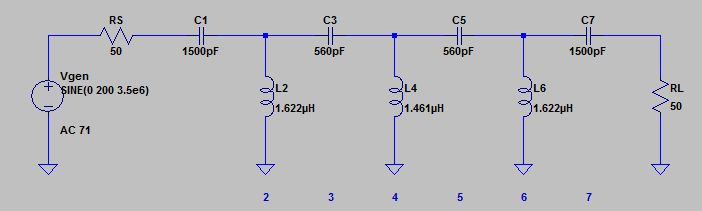
I first modeled a filter using ELSIE free version and found that a 7-pole Chebychev filter looked like it would do the job. I set the cutoff frequency to just below 3.5MHz as I am unlikely to get on 160m with the space I have available. The model indicated that I should be at least 40 dB down by 1.7MHz which should be sufficient.
The circuit is as follows (as drawn in LT SPICE):
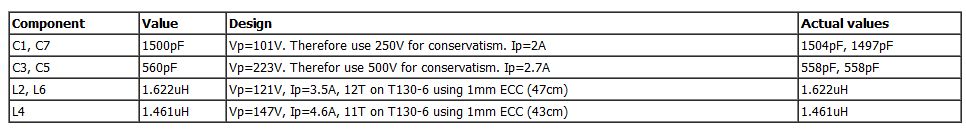
The following table has the component values and expected component currents and voltages at 100W. It also has the winding details for the inductors (note that the wire lengths are for the winding itself – add maybe 10cm to leave enough for connections to other components). I used type 6 material to ensure good performance to at least the top of the HF band and the T130 size is large enough to avoid saturation at 100W. The 1 mm enamelled wire keeps the RF resistance low to reduce loss. The capacitors are 500V silver mica units which have been used many times in 100W class filters over the years and proven reliable.
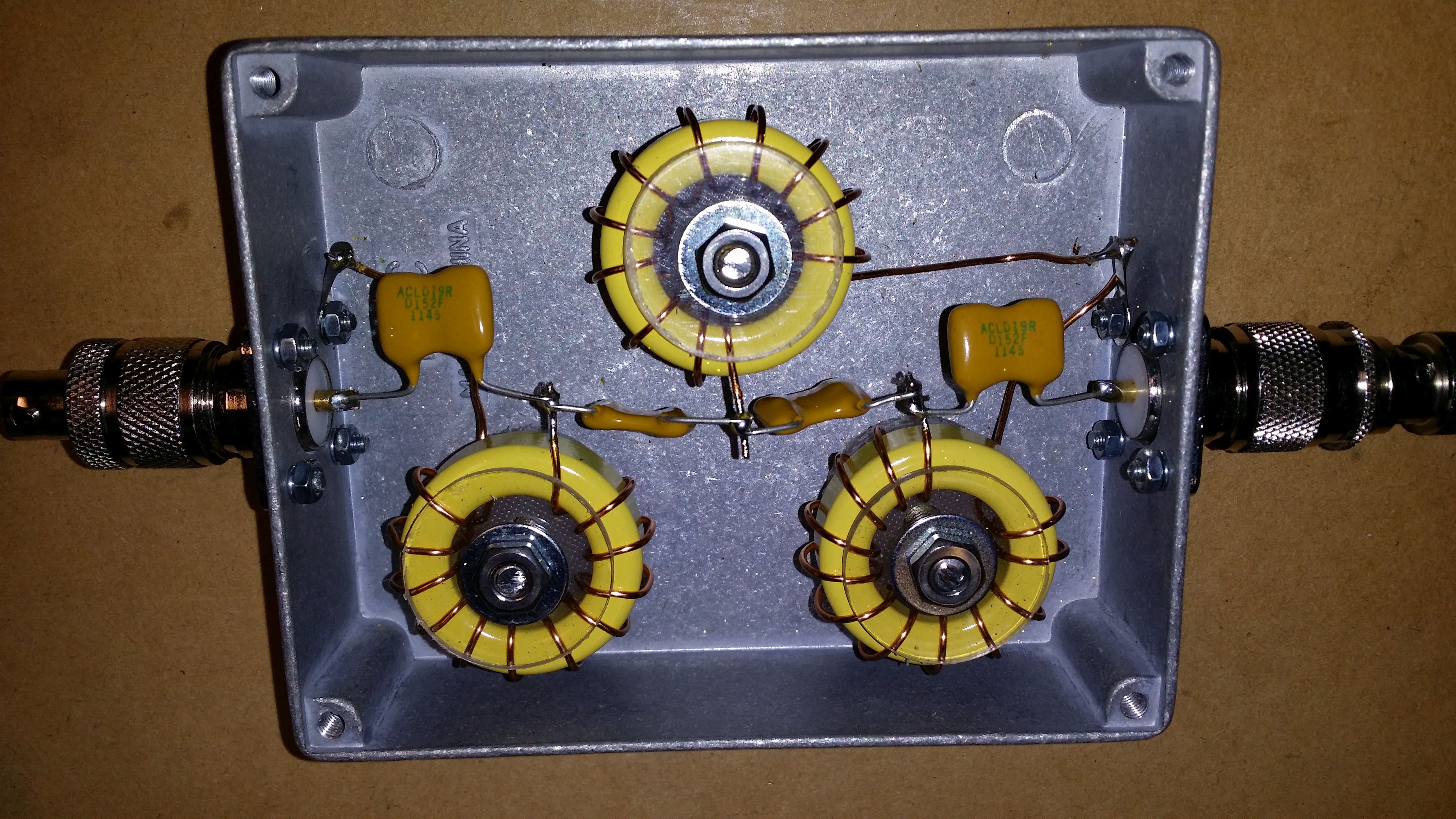
I built the filter in a simple diecast box mounting the inductors using discs of kitchen polyethylene chopping board to separate them from the box. The other components are simply wired point-point with SO239 sockets on each end of the box. The unit is completely symmetrical, so it doesn’t matter which way round it goes.
 This has been tested to 100W with 2 min carrier into a dummy load leading to only mild heating of the capacitors on all bands from 80m through 10m.
I put the filter on my N2PK VNA and was pleased with it’s actual performance as indicated in the following traces:
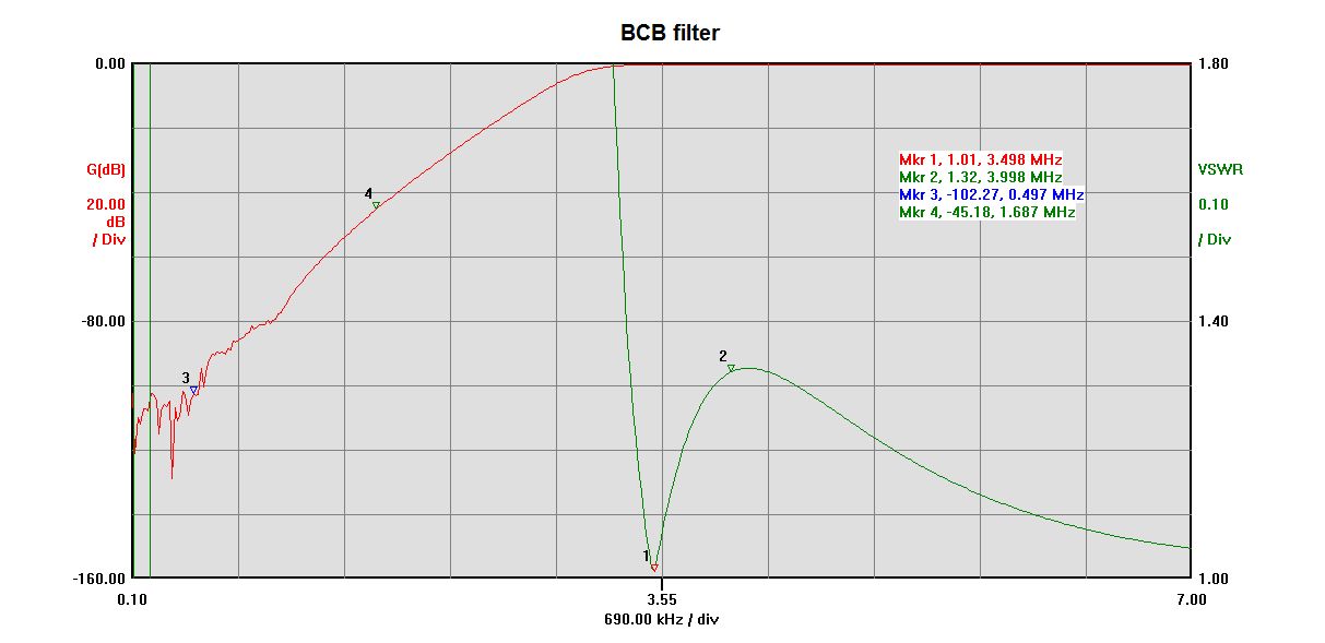
Basic trace of the filter showing more than 100dB down by the bottom of the broadcast band and a respectable 45dB down at the top
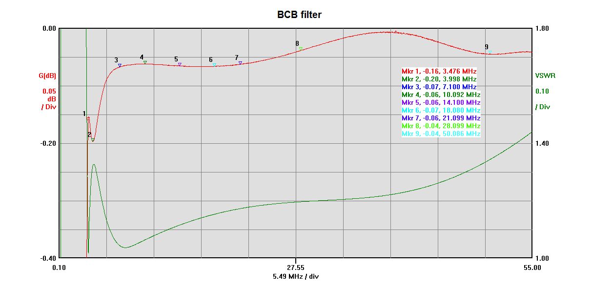
This is an expanded view of the insertion loss across the band to 55MHz. Above 80m, it is less than 0.07dB which is excellent. on the 80m band it peaks at 0.2dB which is still quite acceptable.
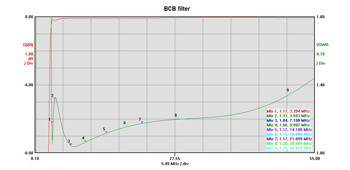
This plot shows the SWR across the band. Apart from 80m, the HF band SWR is better than 1.2:1. On 80m, the peak SWR is 1.3:1 and on 6m it rises to 1.35:1 – still quite usable.
The final test was to look at the broadcast band with the filter in-line. Here’s the plot:
Broadcast band interference with the BCB filter in-line.
As you can see, the interference has been dramatically reduced with the strongest signal now at -81 dBm (about S7) – about 72 dB better than without the filter. Needless to say, the KN-Q7A now works well with the loop antenna.
Hi again David,
I note you have updated your site re the 100 watt capability. Good on yer!
Now to be a bother again, I have been attempting to characterise some Jaycar toroids to use in your design, but have onus that they have a very high Al value and aren’t really suitable for the required inductance values. So, my question is where did you get the FT 130-6 Amidon toroids from? I have t68-2, but I don’t think they would handle the 100watt level.
I am about to check out tts systems but I haven’t seen reference to the 130 size on their web site. Any advice /guidance would be most appreciated.
Regards
Frank
VK1VK
Frank,
Yes, the T68-2 toroids would saturate badly at 100W. Also the type 6 material is lower loss across most of the HF bands, so a better choice in my opinion than type 2.
I obtained my cores from kitsandparts.com in the USA which has very good prices for cores, but is offset by shipping costs. If you think you’ll be needing quite a few cores for different projects, then buying a selection from that site can be good value. Not so much if you only want 3 cores. Locally, TTS may have them or could get them, but minikits.com.au in Adelaide has them in stock.
73
David
VK3IL
Many thanks David. I called tts and they had them so have ordered same from them.
Sorry about the typos in my earlier email!
I’ll keep my ears open for your callsign. I’m often on 40metres in the evenings.
73
Frank
VK1VK
No problems. I don’t get on much of an evening due to long work hours and family commitments, but I’ll keep an ear out.
73
David
VK3IL
Hello David, thanks for sharing your effort and time.
May i ask if its okay if i’m going to use the T130-2 or T106-2 instead of your recommended toroid since thats the only toroid i have here.
Jundy, DV9HF
Hi Jundy,
Thanks for your interest in the article. Type 2 mix toroids will likely work fine, but may be more lossy on the higher bands. If they are what you have available, I would certainly give them a try. If you want to run 100W, I would use the T130-2 rather than the T106-2 which may get close to saturation at full power. If you are only using low power, then the T106-2 would be fine. Note that you will need to change the number of turns on the toroids to achieve the required inductance values with the different cores. Best approach here is to use an LCR meter to measure the the inductors and add/subtract turns until you get the right values. Note that spreading the turns out or bunching them together will move the inductance value too.
73 David VK3IL
Thank you so much for the quick reply and i think i’m gonna use your recommended specs of torroid. But you’re right, the shipping is costly all the way here to our country.
I’d like to draw your attention to an article in the August 2016 issue of Amateur Radio CQ Magazine. It’s on pages 38 – 41. “A Cheap and Easy BCI Filter” by Jack Purdum, W8TEE.
The circuit and component values are identical to yours.
RICH WA6KNW
Thanks Rich. Yes, I knew Jack was writing that article and I gave my permission to use my design. Haven’t seen the final article as I don’t subscribe to CQ, but will look out for it.
A friend is having BCB problems and we are going to build a filter from your design. A quick question, I happen to have some .0015 orange dip 630V Metal-Foil Polypropylene Film caps in the stash. OK to use these or should I use Mica caps?
Thanks!
Jonathan – KK6RPX
Hi Jonathan,
I’m not too familiar with the characteristics of this type of capacitor, so not absolutely sure, but they look like they may be OK. Voltage rating is fine. Question is how they would stand up to transmitting current. I’m guessing they would be OK. Other possible problem would be if they were too inductive, but manufacturers try to minimise inductance, so probably OK. If you can find a data sheet, that would help. In particular, look for the SRF (self resonant frequency). You’d want that to be well above your operating frequency. If you have suitable test equipment available, you can simply give it a try and measure the filter characteristic. Also check for temperature rise after a transmit carrier is applied for 30s or so.
73
David
VK3IL
David,
Thanks! I don’t really have the right equipment to properly test so I probably ought to just use the mica caps. You know how it is, a project using parts out of the junk box just tastes better. 🙂 I’ll order up the cores and caps.
Yes, that’s probably the safest route. Good luck!
Got the filter built yesterday and boy does it wipe out the BCB! We used 576 pF caps instead of the 560’s because that is what my friend ordered. A question: The SWR is a little high, 1.7:1, on the lower half of 80 meters. By the phone portion of the band, say 3.6mHz it drops back to good. Is this likely an effect of the change in cap values? This gives me a push to learning SPICE as I’d like to be able to answer that question myself.
Thanks for the time and effort of your write up on this filter. We ran out of time to really characterize the filter with what primitive tools we have at hand but it clearly knocks the stuffing out of signals below 3mHz!
Glad to hear it’s working for you. The SWR will be higher near the bottom of 80m as you are getting very close to the cut-off frequency. The extra 16pF could well be the cause of the slightly higher value. You could either replace the 576pF with 560pF, or perhaps easier try adjust the turn spacing of the middle inductor. This will increase (closer together) or decrease (more evenly spaced) the inductance a bit and will likely change the SWR at the low end. According to a quick bit of modelling, decreasing that inductance a bit should help, but taking a whole turn off will likely be too much. You could however try removing 1 turn and then bunching up the windings. If all else fails, 1.7:1 is livable with.
Thanks for the reply. I think just getting the right caps makes the most sense, but my friend is not at this point operating CW so leaving it as is would be fine. Thanks again for the write up on the filter!
This filter looks like another project for me.
However, closest BC station is about 30 miles away.
And I would need to take it out of line at times, as I try to work 160 meters once in a while.
Wayne WA2YNE
Thanks for the interest Wayne. Yes, you would definitely need to remove it to use 160m. Designing a filter sharp enough to provide significant attenuation on the BC band and still allowing use of 160m is quite challenging. Not something I need at present as I don’t have room for 160m antennas at my QTH.
You can made a one, usable in 160 meters too; with 100 Watts cappability. LU1AR
Look at this site:
https://www.bnk94.com/w0qe/Projects/100W_160m_broadcast_filter.html
Thanks Maffia. Yes, certainly possible to build one to include 160m if you use a higher order filter as per the design you reference.
I built this last night. The AM station 2 miles away from me that was destroying 40 and 80 meters is gone! Low SWR as well. Thank you for sharing.
Thanks Dave, I’m glad it has worked for you.
Hi David,
I was very pleased to find your well documented project.
It seems there might be a small anomaly. The toroids specify are T130-4 however when I do the calculation the inductances obtained don’t work out to the values you mention. When I use T108-6 instead of the T130-6 then the inductance appears to be as you specified.
Not to sure what to make of this…..
https://toroids.info/T106-6.php
Kind Regards
Pierre ZS6A
Hi Pierre,
Yes, I often find that calculators for toroids tend to give somewhat different results from reality. The actual inductance is affected by the winding spacing and the tolerance in the toroid mix. In practice, use the design data to get in the right ball park and then use turn spacing and adding or subtracting turns to get close to the specified inductance as measured with a LCR meter.
73 David VK3IL
Hi David,
I have three AM stations within 3k of me decimating 80/40 mtr on my IC-7300 built the unit as specified and it has removed all trace of interference much to my delight. thanks for putting the article out there. Bill VK4NBP
Thanks Bill. I’m pleased that it has worked for you.
Worked very well for me! I like to build direct-conversion receivers and live less than a mile from a 20,000 watt AM radio station – a bad combination. This knocked it out completely. THANK YOU!
Thanks Kate. I’m glad it worked out so well for you.
73 David VK3IL
Hi David, Just wanted to let you know you are still relevant!
I picked up a G90 today, and being 1.5 miles from a 50 KW AM station could not hear a thing.
So I used your design, albeit with T80-6s (the only ones on hand) for this 20 watt radio, and it works great, no IMD, no measurable SWR issues, and lots of contacts.
Thanks for posting the design.
73 Scott ka9p
Thanks for your interest Scott, it’s a simple project but really makes a difference when you need it!
73 David VK3IL
How far down in frequency will this attenuate? I’m wanting to squash high voltage overhead power line noise. It seems to be all over anymore.
Hi Nathan,
In theory, this should keep attenuating all the way to DC. As you can see in the plots, at 100 kHz it’s about -120dB and will continue to attenuate further as the frequency decreases. Note that the powerline noise you are hearing will likely be noise generated by arcing of various sorts and the frequencies involved will be quite broad band, so a high pass filter like this one probably won’t make any difference as the noise will fall in the passband of the filter. Sorry!
73 David VK3IL
Well I had high hopes it was the primary but thinking about it later it’s prob harmonics of that. So much for this idea. Still gonna do it for a project. Thank you for your reply!!
Hello David.
I would very much like to build your filter, but…. my QTH is exactly 1 mile from a 50kw station on 830khz. My antenna is a 575ft horizontal Loop at 60ft feet fed with open wire line into a balanced tuner. As you can imagine, this antenna picks up a LOT of energy from that 830khz station. I’m a 160 meter operator so that makes it a bit tricky to attenuate the 830khz station while at the same time allowing 160m operation. As it is right now, I can’t use an antenna analyzer because of the extremely strong RF energy on the antenna. I installed Elise and played with some values but regarding insertion loss and SWR, I have no Idea where to go. Is there anyway you might be able to provide an update on your design to allow operation on the 160m band? My only problem is with the 830khz station, and there’s no concern for the upper end of the BCB, so I’m thinking maybe to move the high pass filter down in freq with less attenuation on the upper end?. Thank you very much David.
73 W2BX Winston Salem NC
Hi Glenn,
OK, that’s a challenging situation! Given you have one known interferrer here, rather than a high pass filter, maybe consider a notch filter centred on the frequeny of the broadcaster. This could be as simple as a parallel tuned circuit in series and/or a series tuned circuit in parallel with the transmission line. As long as the Q is high enough, it shouldn’t affect the 160m SWR or insertion loss to badly. Maybe try modelling that in Elise. Unfortunately, I’m rather busy at present, so am unlikely to have time to explore this further for some time.
Good luck!
73 David VK3IL
Hi David and thanks for the reply.
I have experimented with a few tunable notch filters in the past and was able to bring down 830khz quite a bit but it always affected 160m. If my memory serves, 830khz was 60db down while 160m was 10db down. I guess it wasn’t high Q enough although I did use litz wire on homemade slug tuned forms….. and the swr was not good.
I’ll try a notch filter with Elise although I don’t understand the SWR readings I’m seeing in Elise. 10, 8, … does that represent 10 to 1, 8 to 1, etc?
Thanks for your help with this David, I really appreciate it.
Hi Glenn,
OK, I had a play in Elsie too. The SWR values are xx:1, so a value of 10 is equivalent to 10:1 SWR. I think a solution is possible. I found the following parameters look like they will give an acceptable result:
Butterworth series-input bandstop filter, centre frequency: 830 kHz, 3dB bandwidth: 150kHz, order: 2, Input termination: 50 ohms. This provides a 60+ dB notch with negligible attenuation on 160m and a VSWR of 1.03:1.
73 David VK3IL
I’m thinking of building this project as my Xiegu G90 has problems on the 40m band from a nearby ABC AM station. It seems minikits.com.au no longer stock the T-130-6 toroid, with the next closest toroid being the T-106-6.
I’m assuming this toroid can still be used with an adjustment in turns but it will have a lower power handling ? Do you have any idea what the power handling would be and would stacking two of these together achieve handling 100 watts ?
For me the power handling is not critical as i can connect this filter between my G90 and a 100 watt amplifier.
Thanks for your advice.
Derek VK6DRK
Hi Derek,
Thanks for your interest in the project.
Yes, you could certainly use the T-106-6 toroid with suitable adjustments to the turns to get to the same inductance.
The power handling capability is roughly proportional to the volume of core material of a given type. The T130 size toroid has a core volume of around 6080 cu mm. The T106 size has a core volume of around 4480 cu mm. So two stacked T106-6 should easily give you 100W power handling.
Whilst it wasn’t available when I originally wrote this article, there is a very neat toroid calculator by VK3CPU here: https://miguelvaca.github.io/vk3cpu/toroid.html that you may find helful.
73 David VK3IL