
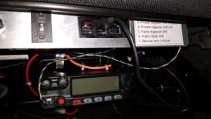
 I have been working on setting up my new Ford Everest for Amateur Radio and in particular, activating SOTA peaks. One of the things I wanted to be able to do was enable APRS tracking to allow chasers to follow my progress to a summit. Given that SOTA peaks are sometimes remote, I wanted to be able to support a high power digipeater from the car to digipeat my APRS-enabled HT. The simple way to do this would have been to buy a Kenwood TM-D710 which has all this built in. However, I like building things, and I’d read about a great piece of open-source software – Direwolf – which can turn a Raspberry Pi into a very versatile tracker/digipeater/iGate with apparently excellent decoding performance.
The main addition required to the Raspberry Pi to turn it into a fully-fledged APRS TNC is a radio interface. As it turns out, there’s a commercially available HAT for the Rapberry Pi designed for just this purpose: North West Radio UDRC II. This is designed primarily for interfacing the Raspberry Pi to a Yaesu DR-1X repeater to add D-Star to it, but it has all the functions necessary to interface two separate radios. It also has a 12V regulator to enable the Raspberry Pi to be powered from a 12V source.
[Update January 2019: The UDRC II HAT is no longer available from North West Radio. They have replaced it with a more capable DRAWS HAT which includes a GPS module and will make this project slightly more integrated. Most of this article is still relevant for the new HAT, but note the following:
- The HD15 connector has been replaced with a second mini-DIN connector and a separate accessory socket. This should in fact simplify the wiring with the accessory socket connecting only to the thumbwheel and the mini-DIN connecting to the second radio. I haven’t checked the mapping of the accesory socket lines to RPi GPIO lines, so you will need to do that.
- The inbuilt GPS should be usable for position data, but you may want to use the external antenna depending on where you plan to place the unit.
- The board also includes a battery backed RTC which simplifies the setting of the system clock. The section below on setting the RPi clock from the GPS is probably no longer relevant.
I haven’t obtained a DRAWS board, so haven’t verified the details above myself.]
The ability to support two radios also opens the possibility to run an even more versatile setup – VHF and HF. I have a IC-7100 as the main car radio and I’ve installed a FT-2900R as a dedicated APRS 75W 2m radio (a cheap, but rugged and high power radio).
I’ve based the design on the Raspberry Pi model 3 as the UDRC only works on a Pi 2 or Pi 3. This has the added benefit of built in WiFi and Bluetooth and a powerful enough processor to easily run Direwolf with a high audio sample rate and any other applications that may be useful. The WiFi in particular allows you to use any modern mobile phone to provide the Pi an Internet connection and thus enable it as an iGate too!
In my case, I wanted to be able to run the setup in a number of different modes depending on what I was doing. I also didn’t want to have to connect a screen and keyboard to the Raspberry Pi to re-configure it. Hence, I implemented a 10 position thumbwheel switch on the front panel to enable simple re-configuration of the system.
Below I document how this is all configured to help anyone else who is interested in going down this path – sorry for the voluminous post, but there are a lot of details to cover!
Hardware setup

Raspberry Pi system built into a simple chassis for vehicle mounting (in my case it’s mounted to the underside of the driver’s seat)
The hardware components for the full mobile installation are:
- HF Radio (IC-7100 in my case) with data port
- VHF Radio (FT-2900R in my case)
- Raspberry Pi 3
- UDRC II HAT (no longer available – DRAWS HAT should work as an alternative)
- Case to suit Raspberry Pi with attached HAT (modify one of the many available)
- 12V DC 100A solid state relay (obtained from eBay – Fotek SSR-100 DD)
- 10 position, BCD coded thumb switch with complementary outputs (e.g: Hartmann DPS9-141-AK2) plus mounting cheeks
- Toggle switch for relay control
- 6-pin mini-DIN to 6-pin mini DIN cable for HF radio (modified so only pins 1-4 are connected)
- HD-15 plug to VHF radio and 12V power cable (custom build this – see below)
- USB GPS (many options – I used a cheap eBay model based on ublox-7 chip)
- Compact USB memory stick (to hold log files)
The main wiring required is to connect the thumb wheel switch, power and radio to the HD15 connector on UDRC. The wiring is as follows:
| HD-15 pin | Function | Connected to |
|---|---|---|
| 1 | GPIO 6 | Thumb wheel BCD 1 complement |
| 2 | PTT | VHF radio PTT line |
| 3 | Unused | |
| 4 | Unused | |
| 5 | Gnd | Gnd, thumbwheel common |
| 6 | Unused | |
| 7 | Audio to radio | VHF radio mic input (twisted pair with gnd) |
| 8 | Unused | |
| 9 | Audio from radio | VHF radio speaker |
| 10 | Gnd | Gnd |
| 11 | GPIO 24 | Thumb wheel BCD 4 complement |
| 12 | GPIO 22 | Thumb wheel BCD 8 complement |
| 13 | Unused | |
| 14 | GPIO 27 (note DIN 6 pin 6 must be open for this to work) | Thumb wheel BCD 2 complement |
| 15 | +12V | +13.8V supply |
The Mini-DIN 6 connector should be wired direct to another Mini-DIN 6 connector to the HF radio, but with only pins 1-4 connected (pins 5 and 6 are shared with pins on the HD-15 that are used for the VHF radio).
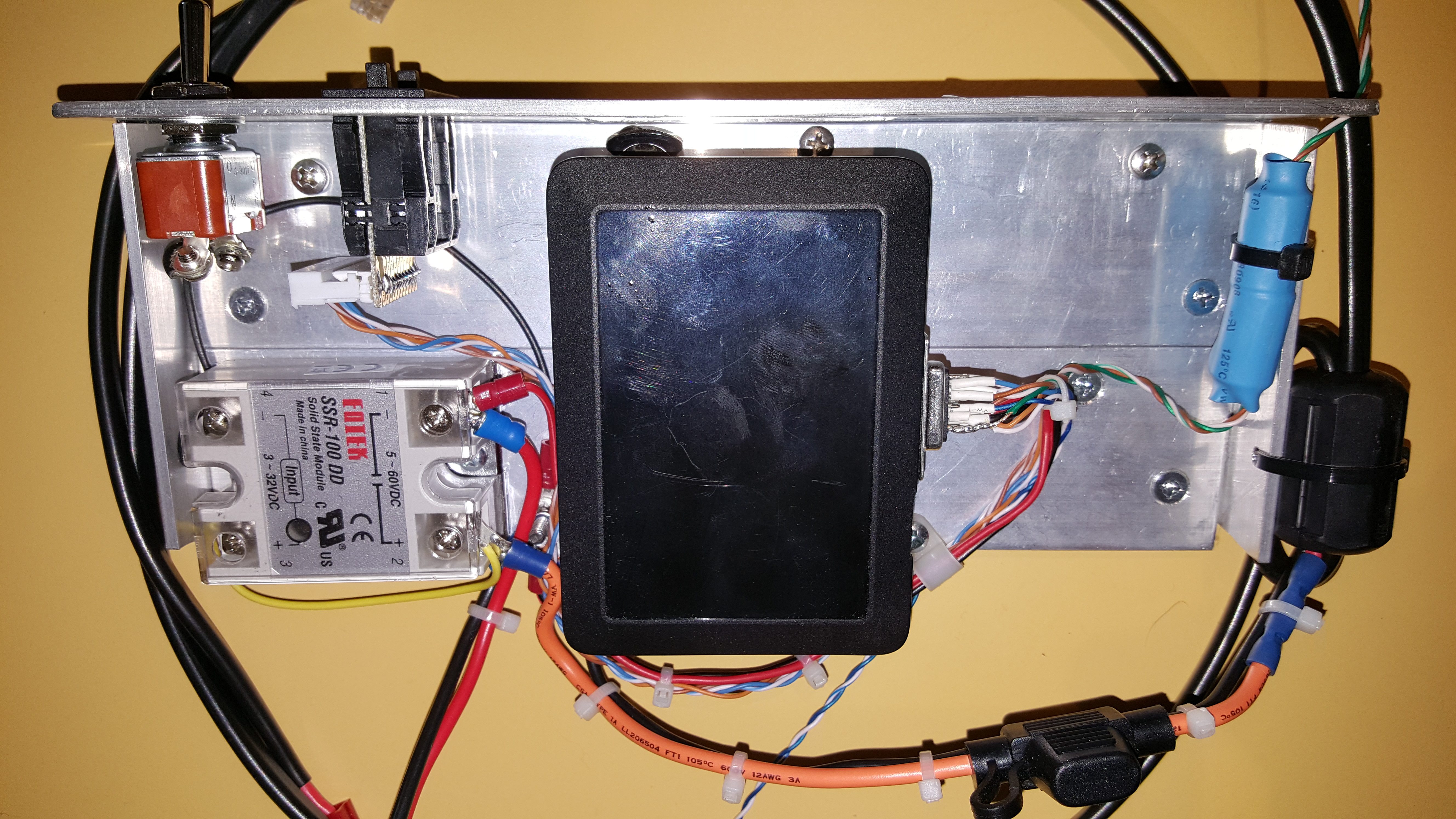
The chassis illustrating the placement of the power switch, SSR, thumbwheel, Raspberry Pi and RF chokes on mic and power leads.
The power wiring uses a solid state relay (SSR) to switch the power to both the Raspberry Pi and VHF radio (and optionally the HF radio). This is a 100A unit which will require some heat sinking if a 100W HF radio is connected through it. With only an APRS dedicated VHF radio, simply attaching it to an aluminium panel should be sufficient due to the low duty cycle. The relay is controlled very simply by a toggle switch.
The radio volume setting and mic gain may need adjusting as per guidelines in the NW Digital Radio UDRC Direwolf notes. Note that the signal levels to and from the UDRC should be within the following maximums:
Output to radio maximum p-p voltage: 1.5V
Input maximum p-p voltage: 1.5V
Raspberry Pi software configuration
Overview
The UDRC card requires some specific tweaks to the standard Raspian kernel and so North West Digital Radio have created their own variant called ‘compass’. This is the basis for the Rapsberry Pi load and needs to be loaded before any other changes.
[Update May 2020: Note that North West Digital Radio no longer supports ‘compass’ as the needed hardware drivers are now in the mainline Linux kernel, so standard Rasbian ‘Buster’ or later should work fine.]
The main other requirements are:
- Load Direwolf and configure it to support mode changing for the various supported use-cases
- Load support for the GPS (to supply tracking data to Direwolf and time to NTP)
- Harden the Raspberry Pi to survive power interruptions without corruption and protect the micro-SD card from early failure
Here are the currently supported operations modes (selected by the thumbwheel):
| BCD value | Mode | Notes |
|---|---|---|
| 0 | Off | |
| 1 | Beacon VHF (+Internet) | Sends normal Smartbeacon signals on VHF radio and also via the internet if available. |
| 2 | Beacon VHF+HF | Sends normal Smartbeacon signals on VHF and HF radio and also via the internet if available. |
| 3 | Private digipeat VHF | Digipeats only my own packets on VHF |
| 4 | Private digipeat VHF+HF | Digipeats only my own packets on VHF and HF radios |
| 5 | Public digipeat VHF | Provides a normal overlay digi function on VHF |
| 6 | Public iGate VHF | Provides a 2-way iGate function |
| 7 | Receive only (+internet) | Only receives packets and forwards them to the Internet if available. |
| 8 | Spare | |
| 9 | Spare |
The following sections document the configuration required to achieve this.
Setting up the OS and Direwolf
First step is to install the ‘compass’ image from North West Radio. Follow the NW Digital Radio instructions here: Loading compass [See note above about compass no longer required]
NW Digital Radio has fairly detailed instructions for loading a standard Direwolf configuration and also enabling the GPS: Installing Direwolf
These instructions are fairly generic and need to be modified for the configuration I describe as detailed below.
Now is a good time to remove any packages that may be less than useful for our application. Obvious ones include libreoffice, games, Mathematica, scratch etc. Also remove the swapfile as we won’t need it for this application:
$sudo systemctl stop dphys-swapfile
$sudo systemctl disable dphys-swapfile
$sudo apt-get purge dphys-swapfile
Before we get too far through the install I need to divert to describe setting up a separate filesystem for the logs and other persistent data that will be a part of hardening the Raspberry Pi (described later). I decided to use a separate small USB stick for keeping logs and other persistent data separate from the main SD card. I chose the btrfs filesystem as it’s supposed to be the best for flash based devices in terms of lowering the number of writes needed. To set this up, insert the blank USB stick into a USB port. You should be able to determine the device assigned to the stick with the ‘df’ command. In my case it identified as /dev/sda. Create the new filesystem as follows:
$sudo apt-get install btrfs-tools
$sudo mkfs.btrfs -m single /dev/sda
Add the new filesystem to the /etc/fstab file mounted on /var/log as follows:
/dev/sda /var/log btrfs defaults 0 1
Supporting Direwolf mode changes from the mode switch
The NW Digital Radio instructions work fine if you only want to run a tracker, a digipeater or iGate. If you want the ability to change them on the fly, you need to be able to shutdown and restart Direwolf with a different configuration file. In my case, I wanted to be able to make this happen in response to the position of the thumb wheel mode switch.
The latest versions of Raspian (including compass) use the SystemD init system and so Direwolf and the mode control software needs to be configured to use this system. SystemD uses “.service” files to specify the characteristics of each service and the actions associated with it.
The first step is to set up Direwolf to use SystemD. This is done by creating a direwolf.service file in /etc/systemd/system. It’s content is:
[Unit]
Description=Direwolf Daemon

[Service]
ExecStart=/usr/bin/direwolf -a 100 -t 0 -c /tmp/direwolf.conf -l /var/log/direwolf
ExecReload=/bin/kill -KILL $MAINPID ; /usr/bin/direwolf -a 100 -t 0 -c /tmp/direwolf.conf -l /var/log/direwolf

[Install]
DefaultInstance=1
$sudo mkdir /var/log/direwolf
You will note that the direwolf config file is located in /tmp as it is a dynamically created file based on the current mode. Note also that this .service file does not automatically start Direwolf as this will be controlled by the mode control script.
Direwolf produces much output to stdout when it is running. As a service, this will end up in syslog unless we do something about it. This can be changed through the rsyslog config file. Create a new file /etc/rsyslog.d/01-direwolf.conf and put the following 2 lines in it:
if $programname == 'direwolf' then /var/log/direwolf/direwolf.log

if $programname == 'direwolf' then ~     # Discards the message after logging in direwolf.log
Activate this with:
$sudo systemctl restart rsyslog
We also need to apply logrotate to this logfile as it will grow rapidly. Create the file /etc/logrotate.d/direwolf with the following content:
 /var/log/direwolf/direwolf.log {
         rotate 7
         daily
         missingok
         notifempty
         delaycompress
         compress
         postrotate
                 invoke-rc.d rsyslog rotate > /dev/null
         endscript
 }
One other utility is needed to enable access to the thumbwheel switch inputs (which are connected to 4 GPIOs that are brought out on the HD15 connector) – WiringPi. This is a package that allows simple control and access to the GPIO pins. In this case, the only component we need is the ‘gpio’ command. WiringPi is pre-loaded in Raspian (and compass), so no extra loading is needed.
The mode control is managed by a separate service: direwolf-mode.service which controls a single script direwolf-mode.sh. The following file controls the service: /etc/systemd/system/direwolf-mode.service
[Unit]
Description=Direwolf mode control Daemon
After=sound.target

[Service]
ExecStart=/usr/local/bin/direwolf-mode.sh
ExecReload=/bin/kill -KILL $MAINPID ; /usr/local/bin/direwolf-mode.sh
Restart=always

[Install]
WantedBy=multi-user.target
DefaultInstance=1
#!/bin/bash
#
# Script to control Direwolf state based on physical switch status
#
# Control switch input is a BCD thumb wheel connected as follows:
# - IO22 - WiringPi: 3 - BCD 8 complement - HD15 pin 12
# - IO24 - WiringPi: 5 - BCD 4 complement - HD15 pin 11
# - IO27 - WiringPi: 2 - BCD 2 complement - HD15 pin 14
# - IO6 - WiringPi: 22 - BCD 1 complement - HD15 pin 1
#
# Modes are as follows:
# 0 - Off
# 1 - Beacon VHF+iGate
# 2 - Beacon VHF+HF+iGate
# 3 - Private digipeat VHF (+iGate)
# 4 - Private digipeat VHF+HF
# 5 - Public digipeat VHF
# 6 - Public iGate VHF
# 7 - Receive only (+iGate)
# 8 - Spare (off)
# 9 - Spare (off)
#
#
# First make sure that the PTT lines are set as output and set to 0 (off)
# Seems to be a problem with a reboot leaving them configured as inputs and drifting high...

/usr/bin/gpio -g mode 12 out
/usr/bin/gpio -g mode 23 out
/usr/bin/gpio -g write 12 0
/usr/bin/gpio -g write 23 0

# Variable 'mode' contains the current state of direwolf
#
# Config files are of the form: /usr/local/bin/direwolf-modeX-config

# First set dummy config file
/bin/echo "# Waiting for GPSD" > /tmp/direwolf.conf

declare -i mode=0
declare -i new_mode

/usr/bin/gpio mode 3 in # BCD 8 complement
/usr/bin/gpio mode 3 up # Enable weak pull-up
/usr/bin/gpio mode 5 in # BCD 4 complement
/usr/bin/gpio mode 5 up # Enable weak pull-up
/usr/bin/gpio mode 2 in # BCD 2 complement
/usr/bin/gpio mode 2 up # Enable weak pull-up
/usr/bin/gpio mode 22 in # BCD 1 complement
/usr/bin/gpio mode 22 up # Enable weak pull-up

# Wait here until gpsd is running as Direwolf won't work properly for tracking unless gpsd is running

while [ ! -e /run/gpsd/gpsd.pid ]; do
 /bin/sleep 5
done

# gpsd started OK, now set a dummy config file

/bin/echo "# Direwolf not started" > /tmp/direwolf.conf

while true; do
 /bin/sleep 5

 # Get the current thumb wheel switch value
 let "new_mode = $(/usr/bin/gpio read 3)"
 let "new_mode = new_mode << 1"
 let "new_mode += $(/usr/bin/gpio read 5)"
 let "new_mode = new_mode << 1"
 let "new_mode += $(/usr/bin/gpio read 2)"
 let "new_mode = new_mode << 1"
 let "new_mode += $(/usr/bin/gpio read 22)"

 if [ $new_mode = $mode ]
 then
 # No change to mode, so just loop
     continue
 fi
 case $new_mode in

 0|8|9|10|11|12|13|14|15)
     # New mode is off or undefined, so change to off mode
     if [ $mode != 0 ]
     then
         systemctl stop direwolf.service
         /bin/echo "# Direwolf stopped" > /tmp/direwolf.conf
         mode=0
     fi
     ;;

 *)
     # Change to new mode by replacing the configuration file and
     # restarting Direwolf
     cp /usr/local/bin/direwolf-mode${new_mode}-config /tmp/direwolf.conf
     systemctl restart direwolf.service
     mode=$new_mode
     ;;

 esac

done
$sudo systemctl enable direwolf-mode.service
As noted in the script above, there seems to be a problem with the PTT lines defaulting to transmit on power up. The script resets them as soon as it starts, but there is still a period while the OS boots where the PTT is active that can result in a carrier being transmitted for a few seconds. Haven’t found a work-around as yet. [Update April 2017: NWDR has come up with a hardware work around for this problem. See this app note.]
Setting up the GPS and providing time to the Raspberry Pi
One of the challenges of running a RPi in a mobile setting where it doesn’t have access to the Internet is maintaining the system time. The Rapberry Pi doesn’t have a battery backup on the clock and relies on syncing to Internet time servers on power up. If there is no Internet connection, the time continues on from a saved value (by fake-hwclock) at the last power down. We have, however, a very accurate time source in the form of GPS and it is not hard to make the Raspberry Pi use this for syncing the system time.
The default version of gpsd in the Raspian distribution (and Compass) seems to be a bit unreliable in updating the shared memory segments. I found I needed to manually install the most recent version of gpsd for reliability. In my case this is v3.16 and it can be downloaded from here: https://download-mirror.savannah.gnu.org/releases/gpsd/
Once gpsd is installed, you can configure NTP to use it as a time source by changing the /etc/ntp.conf file to the following:
 pool au.pool.ntp.org minpoll 8 iburst    # change the pool for your appropriate region

 driftfile /var/log/persistent/ntp.drift
 logfile /var/log/ntp.log

 restrict default kod nomodify notrap nopeer noquery
 restrict 127.0.0.1 mask 255.255.255.0

 # GPS Serial data reference - access via shared memory inter-process communication
 server 127.127.28.0 prefer true
 fudge 127.127.28.0 time1 +0.075 refid GPSD stratum 1

 # time1 +0.075 adjusts for delays through the USB interface (needs to
 # be adjusted for the specific hardware for best accuracy, but not
 # essential for this application)
A complication is that gpsd is by default configured to start only when a client application connects to it and so won’t provide timing information to NTP through the shared memory interface until something like Direwolf connects to it. This can be fixed through the initialisation scripts as follows:
$sudo cp /lib/systemd/system/gpsd.service /etc/systemd/system
Add the following line to /etc/systemd/system/gps.service [Unit] section:
Before=direwolf-mode.service
This makes sure gpsd is started before direwolf-mode service.
Add the following line to /etc/systemd/system/gps.service [Install] section:
WantedBy=multi-user.target
This tells SystemD to start gpsd as part of bringing up the multi-user target (which represent the system up and running in multi-user mode).
Finally tell SystemD that something has changed (rebooting also works) and enable gpsd for automatic start:
$sudo systemctl daemon-reload
$sudo systemctl enable gpsd
You can check that NTP is getting the time from the gps with the following command:
$ntpq -p
The output should look something like this:
  remote refid st t when poll reach delay offset jitter
==============================================================================
+ns2.unico.com.a 27.124.125.252 3 u 81 256 1 0.471 76.026 0.943
+a.pool.ntp.uq.e 27.124.125.252 3 u 80 256 1 0.209 73.916 1.696
+ntp.2000cn.com. 27.124.125.252 3 u 79 256 1 0.466 73.684 1.806
+ntp3.syrahost.c 27.124.125.252 3 u 78 256 1 0.269 73.917 1.426
*SHM(0) .GPSD. 1 l 23 64 3 0.000 69.758 8.381
The asterisk next to the GPS shows that it is the primary source of time. Other lines will only appear if the Raspberry Pi is connected to the Internet.
The final tweak for gpsd is to pass it the -n option which forces the daemon to start querying the gps even before a client connects. This is needed to make sure it is populating the shared memory for ntp when nothing else is using it. This is a simple change to /etc/default/gpsd – just add the -n to the GPSD_OPTIONS variable:
GPSD_OPTIONS="-n"
Hardening the Raspberry Pi
One of the limitations of the Raspberry Pi for embedded applications is that it uses a micro-SD card as its primary storage. The issue is that SD cards have a finite service life based on the number of writes to them. In an application like Linux, there are many writes made to the card as various parameters are updated and this can lead to a relatively short life with random errors and failures appearing over time. A second issue for embedded systems is that Linux is not designed to be arbitrarily stopped with a power switch. This can lead to file corruption and consequent instability.
Overlay filesystem
One of the best ways to mitigate both these issues is to change the root file system to read-only. This would be fine except for all those files that actually need to be written and modified during the normal execution! There is however a neat solution to this problem – Overlay Filesystem – which is now built into the Linux kernel. This is a slightly complex, but very useful capability which creates essentially a merged filesystem with an “upper” and “lower” layer. In our case, we can set the “lower” layer to be the read-only root filesystem and the “upper” layer to be a RAM-based temporary filesystem to store those files that are changed during operation. When the power is cycled, the system will come up in the state of the “lower” file system which is in a clean state.
The final component needed is somewhere to store persistent data that needs to remain across reboots (such as log files and a small number of other variables).
Fortunately, there are a number of scripts around that simplify the creation of such an environment. For this project, I’ve used one created by Pavel Pisa from Czech Technical University, Prague. Here’s a presentation describing it: init-overlay. Setting this up is fairly straight forward:
$cd /sbin
$sudo wget https://github.com/ppisa/rpi-utils/raw/master/init-overlay/sbin/init-overlay
$sudo wget https://github.com/ppisa/rpi-utils/raw/master/init-overlay/sbin/overlayctl
$sudo chmod +x init-overlay overlayctl
$sudo mkdir /overlay
$sudo overlayctl install
$sudo reboot
This is all that’s needed! Read the contents of the two scripts to understand what they are doing if you are interested.
Once the overlay filesystem is active, you can’t update the underlying base system (as it’s read-only). So when you need to make changes, you need to deactivate the overlay filesystem. This is simply accomplished using the ‘overlayctl’ script:
$ sudo overlayctl disable
$ sudo reboot
Similarly, it can be re-enabled:
$ sudo overlayctl enable
$ sudo reboot
Persistent storage
Finally, we need persistent storage for log files etc. Create a directory for other persistent data:
$sudo mkdir /var/log/persistent
$sudo chmod go+wt /var/log/persistent
Key data that needs to be persistent is:
- Saved clock time (fake-hwclock)
- NTP drift file
Fix up fake-hwclock by adding the following to /etc/default/fake-hwclock:
FILE=/var/log/persistent/fake-hwclock.data
We also need to make sure fake-hwclock doesn’t start until the filesystems are mounted. This is achieved by adding to the fake-hwclock.service scripts as follows:
$cd /etc/systemd/system
$sudo cp /lib/systemd/system/fake-hwclock.service .
We then edit the .service file and add the following line to the [Unit] section and comment out the Before= line:
After=local-fs.target
#Before=sysinit.target
The NTP drift file is solved using the line in the ntp.conf file earlier in this article.
Watchdog
Finally we need to harden the pi against random lockups and problems using the hardware watchdog built into the Raspberry Pi. This is a piece of hardware built into the processor that continually counts down a counter – if it ever reaches zero, a hard reset is generated. There is a watchdog daemon that “feeds” the watchdog by reseting the counter periodically. The following commands will enable the watchdog:
$sudo apt-get install watchdog
Modify /etc/watchdog to set the device line as follows:
watchdog-device = /dev/watchdog
Edit the /etc/systemd/system/watchdog.service file to include autostart by copying as follows:
$sudo cp /lib/systemd/system/watchdog.service .
Then edit the file to add this line:
[Install]
WantedBy=multi-user.target
kernel.panic = 10
At this point it would be prudent to take a backup of your SD card in case anything goes wrong in the future. I use the built-in SD Copier command on the accessories menu of the latest release of Raspbian.
That should be all that you need for a high reliability tracker/digipeater/iGate!
Here’s an image from aprs.fi of a recent SOTA expedition to Mt Howitt in the Victorian high country. You will see tracking of the car (orange line) and tracking of my HT (blue line) which was digipeated from the car. Looking at the raw packets, the digipeating of the HT used at least 2 VHF digis and a few HF gateways to provide fairly continuous coverage of the hike.

aprs.fi image of trip to Mt Howitt. Orange is car tracker, blue is HT tracker digipeated from car.
Really appreciative of this – weemingly – comprehensive write up.
I’ve just back ordered a DRAWs board and will attempt the build when it arrives. Many thanks from the UK
Thanks Adam. It will be interesting to see how you go with the DRAWS board – should work fine.
Forgetting the rest, I used your example with just the overlay option, and once I had direwolf running the way I want automatically, enabled overlay. I set up my mobile pi as a ‘hotspot’, and run it with aprsdroid and any other application that supports tcpip kiss tnc. Been working flawlessly for 2 years in a daily driver.
Accurate time and persistent logs are ‘optional’ in this setup.
Thanks for your inspiration.
Thanks Matt. I’m glad it’s worked well for you. I think the overlay filesystem is perfect for using the RPi in embedded applications, very simple to implement and reliable.
We are finding that the aluminum cases with fans and heat sinks help with rfi causing crashes on Pi’s , Was shocked when I mentioned this and got a huge reaction from the Allstar Network Group I just joined on Face Book. They swear by the cases and other boxes. They have had many intermittant problems with RF getting into pi’s.
Michael, thanks for sharing this. I haven’t had any problems with my installation that I’ve attributed to RFI, but certainly could happen. Agree that an aluminium case may well help, but it’s also important to protect the power supply leads and in my case, the mic and speaker audio leads which could be a conduit for conducted RFI into the Pi.
Yes, we have audio from a 10,000 watt transmitter near by getting into a node system. We still need to troubleshoot it further.
Hi
Just getting into this side of APRS having used now two AP510 units both failed after a year or less operating in my car, heat may have been a factor but now unable to program them!!
I am looking at running this 24/7 in my car running mostly VHF but at times HF as well for more remote trips I do (Simpson Desert & CSR)
I ordered a HAT a month or so back that is yet to arrive – may need to chase this soon!
I will be using a Pi4 – they tell me it has less SD Card issues but I like the idea of using a USB stick for the LOG files..
I have played with Linux a few times but have a steep learning curve ahead of me but it’s never a bad thing to get the grey matter working on something new.
Regards
Peter Richens – VK4FSD
Hi Peter,
Yes, this is a very flexible way to run APRS. Should all work well with new HAT and a Pi4. Good luck with it.
73
David
VK3IL